
Method for correcting overall torsional deformation of beam section of steel box girder

A correction method and technology of bridge sections, applied in bridges, bridge construction, bridge parts, etc., can solve problems such as damage, uneconomical, high bending and torsional rigidity, etc.

Active Publication Date: 2021-07-06
四川一宇钢结构工程有限公司 +1
View PDF11 Cites 1 Cited by
  • Summary
  • Abstract
  • Description
  • Claims
  • Application Information

AI Technical Summary

Problems solved by technology

However, the inventors of the present application found in their research that when using local heating in a structure with a large span, it is difficult to determine the heating position, and due to the uneven heating of the structure, a large residual stress will be generated, which will affect its mechanical properties. When the load correction error is applied to a structure with a large span, due to the large overall bending and torsional stiffness of the structure, a large load needs to be applied, which will cause the structure to enter plasticity or even local failure in advance, greatly reducing the The reliability of the structure; in addition, the range of the above two methods can be corrected is limited, when the error is large, it is difficult to meet the requirements
If it is not corrected and reprocessed, it is neither economical nor conducive to production progress.

Method used


Image

  • Method for correcting overall torsional deformation of beam section of steel box girder
  • Method for correcting overall torsional deformation of beam section of steel box girder
  • Method for correcting overall torsional deformation of beam section of steel box girder

Examples


Embodiment

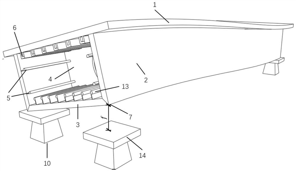
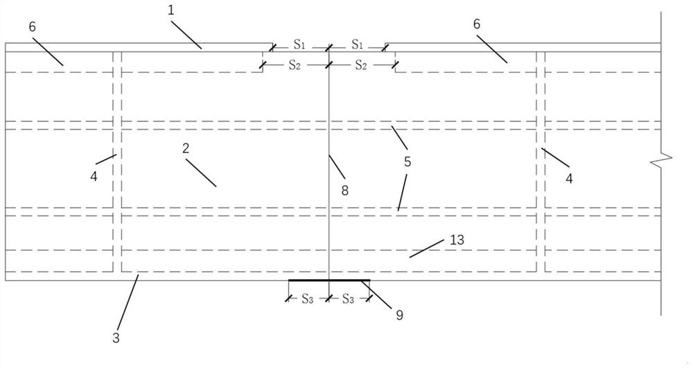
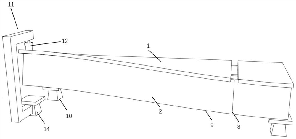
[0053] Such as Figure 1~6 As shown, the length of the beam section is 30m, the beam height is 5m, the distance between the diaphragms 4 is 3m, and the distance between the corner point (suspension) 7 and the fixed support 14 not in contact with the corner point is 240mm.

[0054] Determine the plane position and elevation of the fixed support 10 according to the design coordinates, place the beam section on the fixed support 10, and determine the suspended end of the corner point 7 as the correction end, and the other end as the fixed end.

[0055] Estimated number of revisions

[0056]

[0057] At the middle point of the bridge deck 1 of the segment closest to the fixed end, cut s symmetrically to both sides along the longitudinal direction 1 = 500mm of bridge deck 1, and s 2 = U-shaped rib 6 of 700mm. The above-mentioned cutting length is only a preferred cutting length of the embodiment of the present application, and the cutting length is not limited thereto, but it...


PUM


Abstract

The invention discloses a method for correcting overall torsional deformation of a steel box girder beam section, which comprises the following steps that: a, the plane and elevation arrangement of a fixed support are determined, the beam section is placed and a fixed end and a correction end are determined; b, a bridge deck slab and a U-shaped rib are cut from the midpoint of the first section in the transverse direction; c, a web is cut in the vertical direction, and welding seams of the web and the bottom plate are cut in the longitudinal direction; and d, the fixed end is restrained, forced displacement is applied to the correction end, the maximum distance between the web and the bottom plate at the cut position and whether the correction end supporting point makes contact with the fixed support or not are observed, and the steps b to d are repeated at the next section till the correction end supporting point makes contact with the fixed support. According to the method, the problem that torsional deformation of the large-span steel box girder bridge is difficult to correct is effectively solved, residual strain generated by deformation correction is reduced, re-machining and re-manufacturing are avoided, the construction period is shortened, and the cost is reduced.

Description

technical field [0001] The invention relates to the field of steel structure bridge construction, in particular to a method for correcting the overall torsional deformation of a steel box girder bridge section. Background technique [0002] Steel box girder sections are widely used in various engineering structures due to their advantages such as high bending and torsional rigidity, light weight, and fast construction speed. However, due to its high construction accuracy requirements, the construction level of the construction party is relatively high, and it is inevitable that errors will exceed the limit. There are two main error correction methods: one is to use local heating to deform the structure to correct the error, and the other is to apply a load to the error position to deform the structure to correct the error. However, the inventors of the present application found in their research that when using local heating in a structure with a large span, it is difficult...

Claims


Application Information

Patent Timeline
IPC IPC(8): E01D21/00E01D2/04E01D19/12
CPCE01D21/00E01D2/04E01D19/125Y02P10/20
Inventor 王宽王放李羿辰李开奇余志祥许浒赵雷
Owner 四川一宇钢结构工程有限公司
Learn More