High-speed motorized spindle transient dynamic load simulation loading method and device
A high-speed electric spindle and loading device technology, which is applied in the testing of measuring devices, instruments, and mechanical components, etc., can solve the problems of low flexibility, difficulty in ensuring a small air gap between the loaded object and the electromagnet, and the size of the air gap cannot be adjusted.
- Summary
- Abstract
- Description
- Claims
- Application Information
AI Technical Summary
Problems solved by technology
Method used
Image
Examples
Embodiment 1
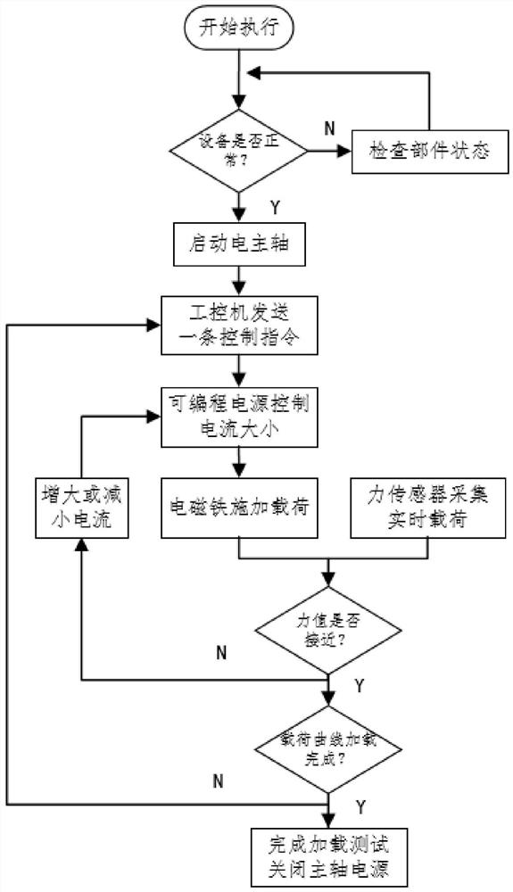
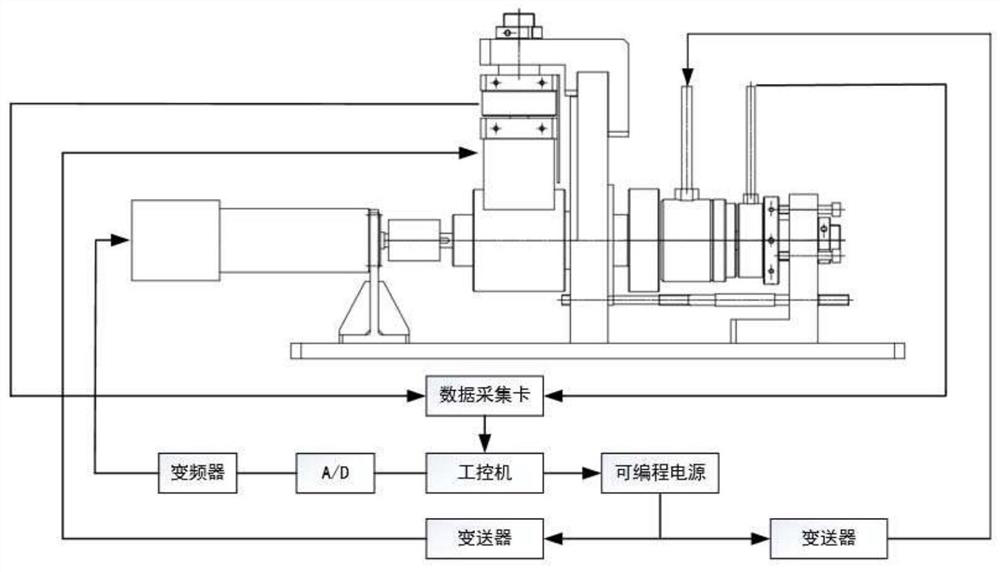
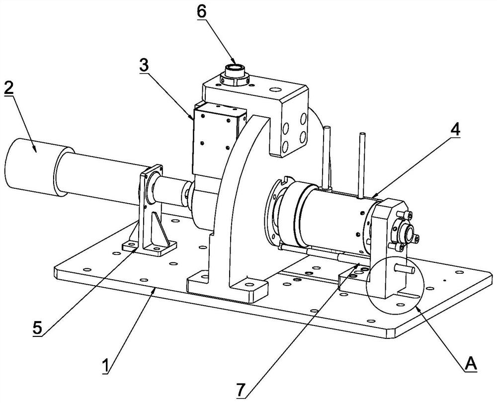
[0044] See Figure 1 - Figure 4 In this embodiment, the present embodiment discloses a high-speed electrical spindle transient movable load analog loading method, including the following steps:
[0045] (1) Adjust the air gap between the arc-shaped electromagnet 3-6 and the radial force shaft 3-2 by the radial force air gap adjustment mechanism 6, and adjust the planar electromagnet 4-4 and the shaft through the axial force air gap adjustment mechanism 7. The air gap between the load disk 4-1; and determine the air gap between the curved electromagnet 3-6 and the radial force shaft 3-2 and the planar electromagnet 4-4 and the axial load disk 4-1. Air gap;
[0046] (2) The detection device is operating normally. If it is normal, the industrial computer starts to work, if not normal, check the state of the components until the device is operating normally;
[0047] (3) After the industrial control machine transmits the control command, after the A / D converter is converted, it is se...
Embodiment 2
[0074] The other configuration in this embodiment is the same as that of the first embodiment, and there is different, and one end of the adjusted rod 9 is rotated to the radial force base 3-1, and the other end and the axial force base 4. -2 is connected by a thread. By rotating the adjustment rod 9, the driving axial force base 4-2 can move along the guide groove 1-1 under the action of the threaded connection, in which the axial load disc 4-1 is in an air of the plane electromagnet 4-4. Gap adjustment.
Embodiment 3
[0076]The other configuration in this embodiment is the same as that of the first embodiment, and the difference is that the specific structure of the axial force air gap adjustment mechanism 7 is the same as the specific structure of the radial air gap adjustment mechanism 6, all by adjusting the bolt adjustment shaft.The position of the planar electromagnet 4-4 and the axial load tray 4-1 is adjusted to the position of the magnetic force shaft 4-3 in the adjustment hole 6-1 of the axial force base 4-2, and then by the lock nut6-2 lock the axial magnetic force shaft 4-3 on the axial force base 4-2.
PUM
 Abstract
Description
Claims
Application Information
 - R&D
- Intellectual Property
- Life Sciences
- Materials
- Tech Scout
- Unparalleled Data Quality
- Higher Quality Content
- 60% Fewer Hallucinations
Browse by: Latest US Patents, China's latest patents, Technical Efficacy Thesaurus, Application Domain, Technology Topic, Popular Technical Reports.
© 2025 PatSnap. All rights reserved.Legal|Privacy policy|Modern Slavery Act Transparency Statement|Sitemap|About US| Contact US: help@patsnap.com


