
Epoxy resin electric power insulator casting molding method

An epoxy resin, pouring molding technology, applied in the direction of insulators, circuits, electrical components, etc., can solve the problems of long mold clamping and demoulding, cumbersome mold clamping and demoulding, damage to circuit service life and operating life, etc.

Inactive Publication Date: 2021-07-06
谭宗尧
View PDF0 Cites 3 Cited by
  • Summary
  • Abstract
  • Description
  • Claims
  • Application Information

AI Technical Summary

Problems solved by technology

Although the structure and shape of different types of insulators are quite different, they are all composed of two parts: insulators and connecting fittings. Insulators are a special insulation control that can play an important role in overhead transmission lines. In the early years Insulators are mostly used on utility poles, and gradually developed in the high-voltage wire connection tower with a lot of disc-shaped insulators hanging at one end. It is to increase the creepage distance. It is usually made of glass or ceramics and is called an insulator. Insulators should not be due to Failure due to various electromechanical stresses caused by changes in the environment and electrical load conditions, otherwise the insulator will not have a significant effect and will damage the service life and operating life of the entire line
[0003] However, the epoxy resin power insulators currently on the market have the following problems in the process of pouring: a. when the epoxy resin power insulators are poured, the mold cannot be quickly clamped and demoulded, and the traditional mold clamping and demoulding The mold is cumbersome, and it takes a long time for mold closing and demoulding, which reduces the applicability and work efficiency of the machine
b. When pouring epoxy resin power insulators, due to the structural limitations of power insulators, the epoxy resin material cannot be quickly flowed into the entire edge of the mold cavity, which reduces the mechanical qualification rate

Method used


Image

  • Epoxy resin electric power insulator casting molding method
  • Epoxy resin electric power insulator casting molding method
  • Epoxy resin electric power insulator casting molding method

Examples


Embodiment Construction

[0035] In order to make the technical problems, technical solutions and beneficial effects to be solved by the present invention clearer, the present invention will be further described in detail below in conjunction with the accompanying drawings and embodiments. It should be understood that the specific embodiments described here are only used to explain the present invention, not to limit the present invention.

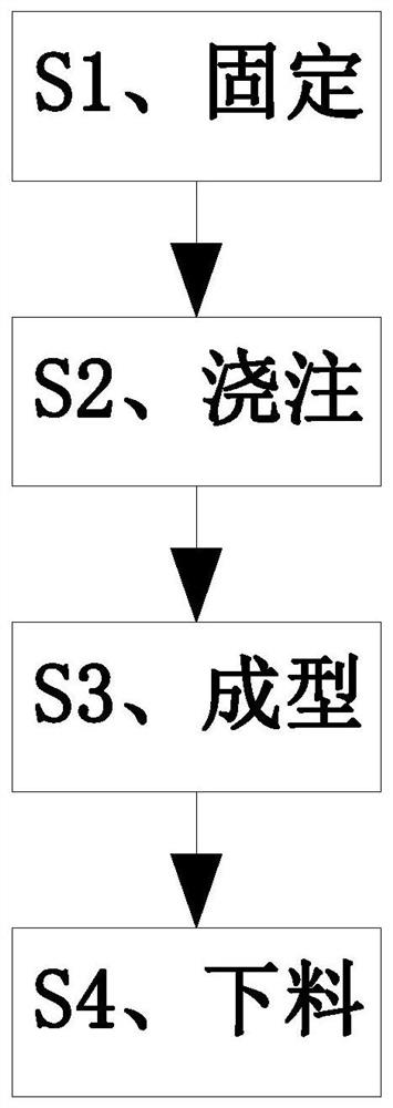
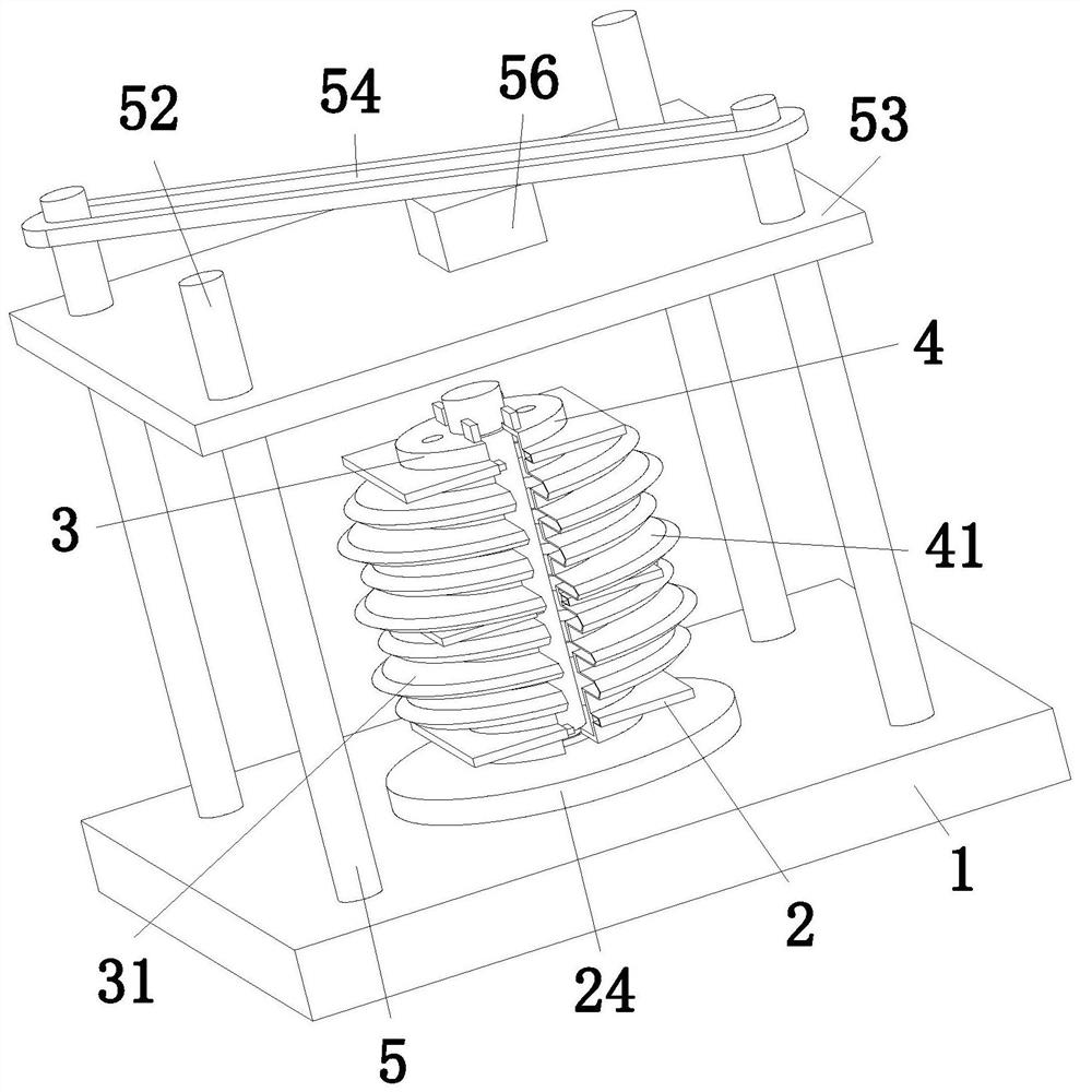
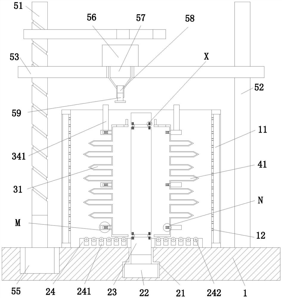
[0036] refer to Figure 1-10As shown, an epoxy resin power insulator pouring molding method, the epoxy resin power insulator pouring molding method specifically includes the following steps:

[0037] S1. Fixing: First, the first mold 3 and the second mold 4 of the epoxy resin power insulator that need to be casted are clamped on the fixing device 2, and the first mold 3 and the second mold 4 are fixed through the fixing device 2. limit;

[0038] S2. Pouring: After the S1 step is completed, when the fixing device 2 limits the first mold 3 and the second mold 4, a ...


PUM


Abstract

The invention relates to an epoxy resin electric power insulator casting molding method, which comprises a workbench, a fixing device, a first mold, a second mold and a moving device, and is characterized in that the fixing device comprises a placing groove, a driving motor, a circular rod, an annular plate, an annular clamping groove and a clamping frame; through cooperation of the workbench, the fixing device, the first mold, the second mold and the moving device, firstly, the first mold and the second mold of the epoxy resin electric power insulator needing to be subjected to casting molding are rapidly closed through the fixing device, so that traditional tedious mold closing and demolding are avoided, and the mechanical adaptability and working efficiency are improved; and the mold cavity is poured through the moving device, and the molten resin material can uniformly flow to the whole edge structure of the mold cavity through the matching of the fixing device, so that the qualified rate of the machine is improved.

Description

technical field [0001] The invention relates to the field of insulators, in particular to an epoxy resin power insulator casting method. Background technique [0002] Insulators are devices installed between conductors at different potentials or between conductors and grounding components that can withstand voltage and mechanical stress. There are many types of insulators and different shapes. Although the structure and shape of different types of insulators are quite different, they are all composed of two parts: insulators and connecting fittings. Insulators are a special insulation control that can play an important role in overhead transmission lines. In the early years Insulators are mostly used on utility poles, and gradually developed in the high-voltage wire connection tower with a lot of disc-shaped insulators hanging at one end. It is to increase the creepage distance. It is usually made of glass or ceramics and is called an insulator. Insulators should not be due ...

Claims


Application Information

Patent Timeline
IPC IPC(8): H01B19/00H01B19/02
CPCH01B19/00H01B19/02
Inventor 谭宗尧
Owner 谭宗尧
Learn More