
Gate Drive Apparatus and Control Method

A technology for gate drive and equipment, applied in the field of gate drive equipment for inverters

Pending Publication Date: 2021-07-06
DIODES INC
View PDF6 Cites 0 Cited by
  • Summary
  • Abstract
  • Description
  • Claims
  • Application Information

AI Technical Summary

Problems solved by technology

The inventors have identified this design inconsistency and worked to resolve it

Method used


Image

  • Gate Drive Apparatus and Control Method
  • Gate Drive Apparatus and Control Method
  • Gate Drive Apparatus and Control Method

Examples


Embodiment Construction

[0024] The invention will be described for a preferred embodiment in the specific context, namely a gate drive circuit for driving an inverter. However, the present invention is also applicable to various power conversion systems. Hereinafter, various embodiments will be described in detail with reference to the accompanying drawings.

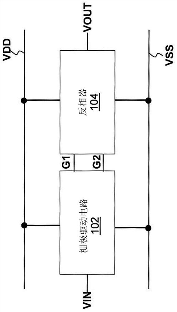
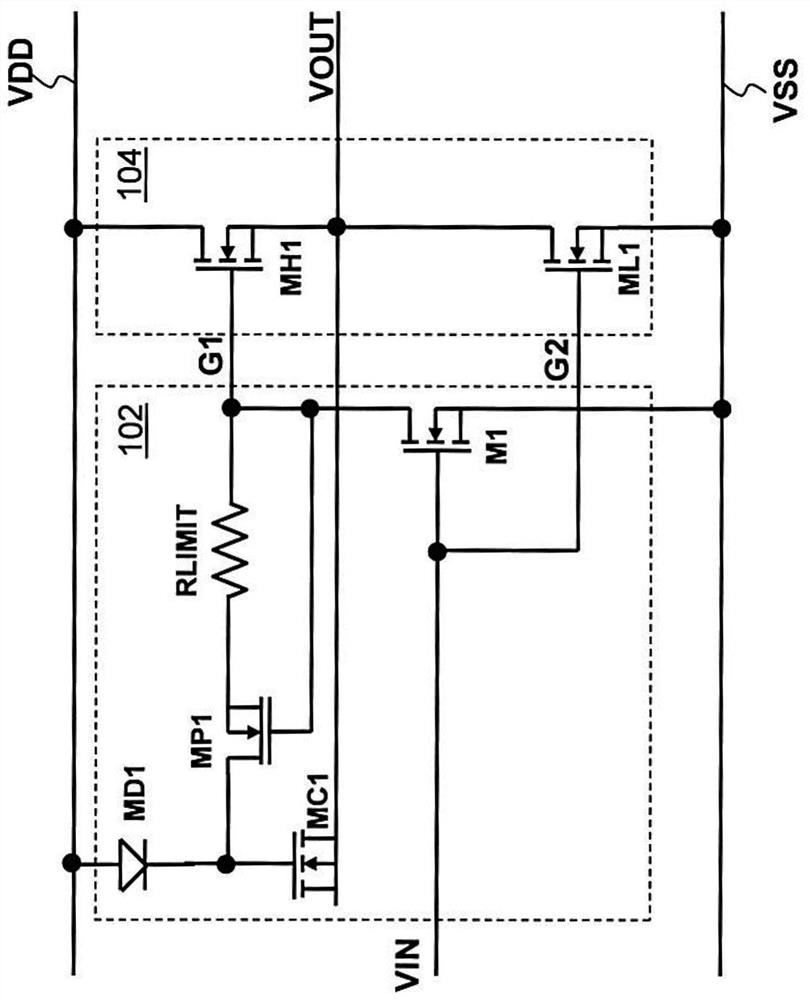
[0025] figure 1 A block diagram of an inverter and its associated gate drive circuitry is depicted. The inverter 104 is connected between the first voltage bus VDD and the second voltage bus VSS. The inverter 104 is configured to receive two gate driving signals, namely a first gate driving signal G1 and a second gate driving signal G2 . The gate driving circuit 102 is connected between the first voltage bus VDD and the second voltage bus VSS. The gate driving circuit 102 is configured to receive an input signal VIN. The gate driving circuit 102 converts the input signal VIN into gate driving signals G1 and G2. figure 1 Gate drive circuit...


PUM


Abstract

The invention relates to a gate drive apparatus and a control method. The apparatus includes a capacitive device configured to provide bias power for a high-side switch, a gate drive path having variable resistance connected between the capacitive device and a gate of the high-side switch, wherein the gate drive path having variable resistance is of a first resistance value in response to a turn-on of the high-side switch, and the gate drive path having variable resistance is of a second resistance value in response to a turn-off of the high-side switch, and wherein the second resistance value is greater than the first resistance value, and a control switch connected between the gate of the high-side switch and ground.

Description

technical field [0001] The present invention relates to a gate drive device, and in a particular embodiment to a gate drive device for an inverter. Background technique [0002] An inverter consists of two switches connected in series between power and ground. Switches connected to power are often referred to as high-side switches, while switches connected to ground are commonly referred to as low-side switches. A high-side driver circuit and a low-side driver circuit are employed to control the gate of the high-side switch and the gate of the low-side switch, respectively. In order to turn on the high side switch, the high side driver circuit may require a gate voltage higher than the voltage of the power supply. This can be achieved using a bootstrap capacitor circuit. [0003] Kinzer (US Patent Application 2017 / 0222644) discloses a GaN gate drive circuit including a bootstrap capacitor configured to drive a high side switch of an inverter. The bootstrap capacitor is c...

Claims


Application Information

Patent Timeline
Patent Type & Authority Applications(China)
IPC IPC(8): H03K17/04
CPCH03K17/04H03K17/04123H03K2217/0081H03K2217/0063H03K2217/0036H03K17/693H03K2017/6875
Inventor 庄乔舜T·郭K-H·陈
Owner DIODES INC
Learn More