Flat pruning equipment for garden pruning
A kind of equipment and garden technology, applied in the field of garden pruning and leveling equipment, which can solve the problems of waste branches and leaves flying everywhere, breathing pollution of workers, harm to health, etc.
- Summary
- Abstract
- Description
- Claims
- Application Information
AI Technical Summary
Problems solved by technology
Method used
Image
Examples
specific Embodiment approach 1
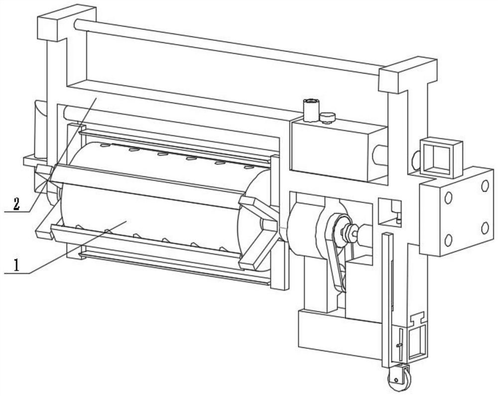
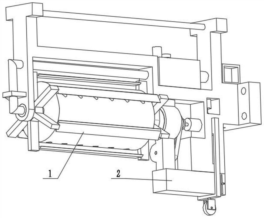
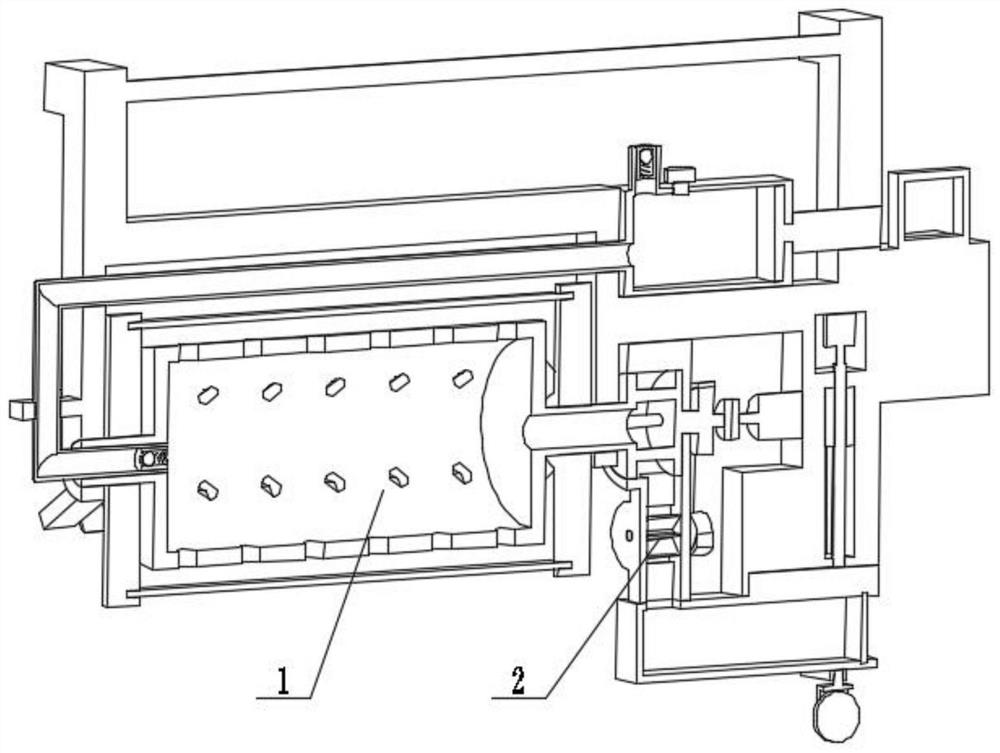
[0025] Combine below figure 1 , figure 2 , image 3 , Figure 4 , Figure 5 , Figure 6 , Figure 7 , Figure 8 , Figure 9 , Figure 10 Describe this embodiment, the present invention relates to a kind of pruning equipment, more specifically a kind of leveling equipment for garden pruning, including a pruning actuator 1, a multi-switch frame mechanism 2, the equipment can perform pruning, and the equipment can recycle the pruned For waste branches and leaves, the equipment can be watered while trimming, and the equipment can adjust the working height and achieve labor-saving effect.
[0026] The trimming actuator 1 is connected with a multi-switch frame mechanism 2 .
specific Embodiment approach 2
[0028] Combine below figure 1 , figure 2 , image 3 , Figure 4 , Figure 5 , Figure 6 , Figure 7 , Figure 8 , Figure 9 , Figure 10 Describe this embodiment, this embodiment will further explain the first embodiment, the trimming actuator 1 includes a cutting knife 1-1, an opening 1-2, a rotating cylinder 1-3, a knife fixing wheel 1-4, and a fixing box 1-5, belt 1-6, shaft pulley 1-7, coupling 1-8, motor 1-9, pulley 1-10, inlet 1-11, rotating disc 1-12, bearing seat 1-13 , inner cavity 1-14, communication channel 1-15, card slot 1-16, disc with connecting rod 1-17, impeller with shaft 1-18, discharge port 1-19, cutting knife 1-1 snapped into card slot 1 In -16, the card slot 1-16 is arranged on the tool fixed wheel 1-4, and the tool fixed wheel 1-4 is symmetrically arranged on both sides of the rotating cylinder 1-3, and one end of the rotating cylinder 1-3 is provided with a rotating disk 1-12 , the rotating disk 1-12 is rotationally connected with the bearing...
specific Embodiment approach 3
[0030] Combine below figure 1 , figure 2 , image 3 , Figure 4 , Figure 5 , Figure 6 , Figure 7 , Figure 8 , Figure 9 , Figure 10This embodiment will be described. This embodiment will further describe the first embodiment. The multi-switch frame mechanism 2 includes a discharge check valve 2-1, a conduit 2-2, a frame body 2-3, a handle 2-4, Water tank 2-5, intake valve 2-6, intake pipe 2-7, screw plug 2-8, hydraulic cylinder 2-9, handle 2-10, bolt hole 2-11, servo motor 2-12, floating frame 2 -13, Embedding groove 2-14, collection box 2-15, air outlet 2-16, filter plate 2-17, universal wheel 2-18, inner piston 2-19, hydraulic rod 2-20, lead screw 2- 21. Threaded hole 2-22, adjustment groove 2-23, waste material inlet 2-24, ejection check valve 2-1 is arranged in conduit 2-2, conduit 2-2 is connected with frame body 2-3, conduit 2 One end of -2 is inserted into the entrance 1-11, the conduit 2-2 is rotatably connected to the rotating cylinder 1-3, the handle ...
PUM
 Abstract
Description
Claims
Application Information
 - R&D
- Intellectual Property
- Life Sciences
- Materials
- Tech Scout
- Unparalleled Data Quality
- Higher Quality Content
- 60% Fewer Hallucinations
Browse by: Latest US Patents, China's latest patents, Technical Efficacy Thesaurus, Application Domain, Technology Topic, Popular Technical Reports.
© 2025 PatSnap. All rights reserved.Legal|Privacy policy|Modern Slavery Act Transparency Statement|Sitemap|About US| Contact US: help@patsnap.com


