Method for preoperative screening of position where nerve stimulator is implanted into skull and system thereof

A technology of nerve stimulation and implantation, applied in surgical navigation systems, surgery, instruments, etc., can solve problems such as affecting wound healing, prolonging operation time, and sutured skin tension, so as to solve difficulties and complications, and reduce surgery. time, the effect of reducing side effects

Active Publication Date: 2021-07-09
SCENERAY
8 Cites 1 Cited by

AI-Extracted Technical Summary

Problems solved by technology

Currently, Neuropace's cranial nerve stimulators are commonly implanted in the parietal bone and the occipital bone. Usually, the neurosurgeon compares the shape of the patient's skull with the shape of the neurostimulator during the operation. Perform craniotomy after the approximate range, and adapt to the shape of the neurostimulator while removing the skull, which will lead to prolonged operation time
More importantly, due to the existence of individual differences, this adaptation is often not realized in the practical application of clinical surgery. It is shown that part of the neurostimulator fits well with the skull, and part of it ...

Method used

In summary, the present invention utilizes the 3D appearance model of neural stimulator and the 3D structure calculation neural stimulator of patient's cranium to plan to implant the adaptation coefficient of cranial region of interest, determines that neural stimulator intends to implant skull according to adaptation coefficient The optimal position of the skull implantation neurostimulator can be screened before operation. On the one hand, it can allow doctors to select the optimal implantation position of the individ...

Abstract

The invention relates to a method for preoperative screening of a position where a nerve stimulator is implanted into a skull and a system thereof. The method comprises the following steps: acquiring image data of the skull of a patient and a 3D appearance model of the nerve stimulator; reconstructing a 3D structure of the skull of the patient according to the image data; utilizing the 3D appearance model of the nerve stimulator and the 3D structure of the skull of the patient to calculate the adaptation coefficient of the nerve stimulator to be implanted into the skull region of interest; and determining the optimal position of the nerve stimulator to be implanted into the skull according to the adaptation coefficient. According to the method, the implantation position of the skull implanted into the nerve stimulator is screened before the operation, on one hand, the individualized optimal skull implantation position can be selected according to the individual difference of patients before the operation, the operation time is shortened, on the other hand, the matching condition of the implanted nerve stimulator and the skull can be truly demonstrated and evaluated, individual adaptation of the nerve stimulator and the skull is truly achieved, safety after implantation is guaranteed to the maximum extent, and the problems of difficulty and complications of implantation of the existing nerve stimulator into the skull are solved.

Application Domain

Surgical navigation systemsComputer-aided planning/modelling +1

Technology Topic

Nerve stimulatorsSkull bone +6

Image

  • Method for preoperative screening of position where nerve stimulator is implanted into skull and system thereof
  • Method for preoperative screening of position where nerve stimulator is implanted into skull and system thereof

Examples

  • Experimental program(1)

Example Embodiment

[0034] The present invention will be further described below in conjunction with the accompanying drawings and specific embodiments, so that those skilled in the art can better understand the present invention and implement it, but the examples given are not intended to limit the present invention.
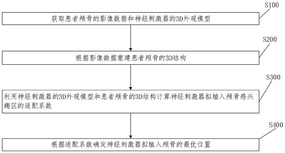
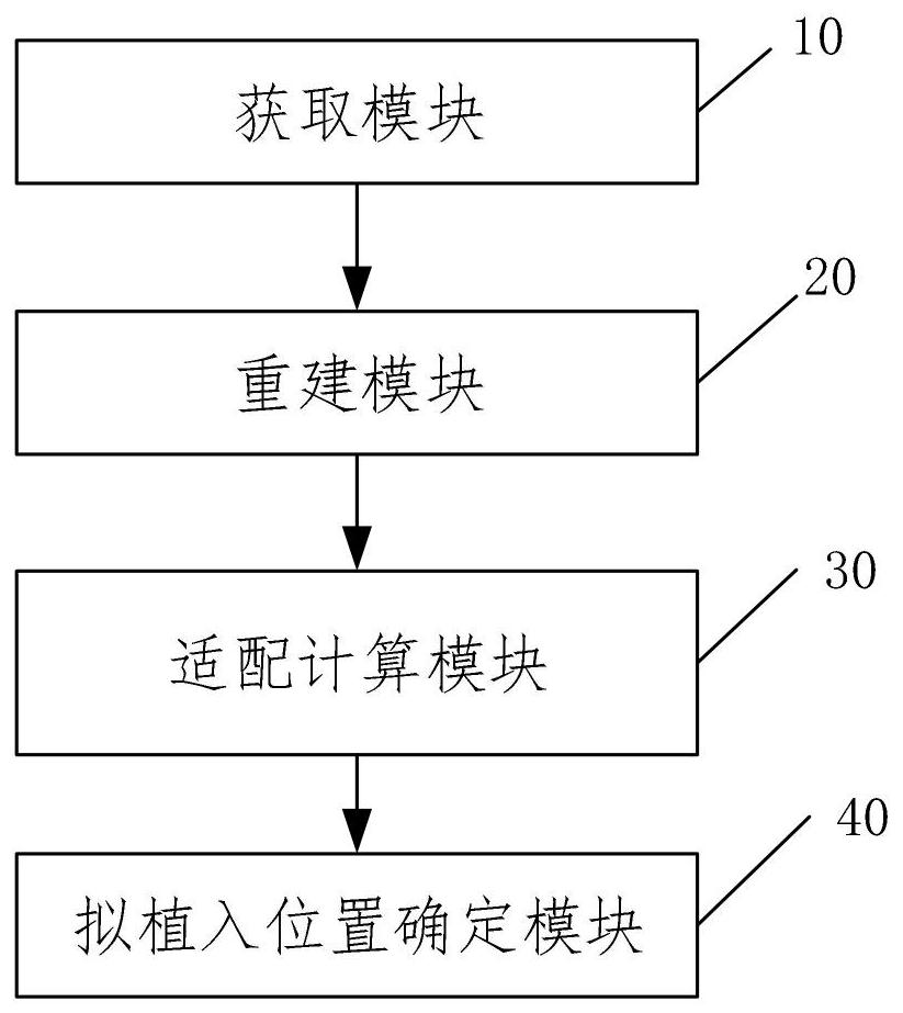
[0035] In order to better understand a method and system for preoperatively screening the position of a neurostimulator implanted in the skull disclosed in the embodiment of the present invention, the present invention provides figure 1 Schematic flow diagram of the method for preoperative screening of the placement of neurostimulators in the skull is shown.
[0036] see figure 1 As shown, the embodiment of the present invention is a method for preoperatively screening the implantation position of the neurostimulator in the skull, the method comprising the following steps:
[0037] Step 100: Obtain image data of the patient's skull and a 3D appearance model of the neurostimulator.
[0038] For example, the image data can be CT data. The patient can scan the head CT to obtain the CT data of the tissue image and the skull bone window image dicom. The CT data here can be burned on a CD for backup, and of course it can also be MRI. The present invention is not limited thereto.
[0039] For example, a 3D appearance model of a neurostimulator can be constructed using software, such as CREO, and the 3D appearance model of the same neurostimulator can be backed up for different individuals.
[0040] Step 200: Reconstruct the 3D structure of the patient's skull according to the image data.
[0041] Exemplarily, the image data may be CT data, and the CT data of the patient's skull is imported into the software. For example, MimicsMedical software reconstructs the 3D structure of the patient's skull for backup, specifically importing dicom data—selecting the skull threshold range—constructing the 3D structure of the skull.
[0042] Step 300: Using the 3D appearance model of the neurostimulator and the 3D structure of the patient's skull to calculate the adaptation coefficient of the neurostimulator to be implanted into the region of interest of the skull.
[0043] As an example, construct a neural stimulator and an adaptation calculation model to be implanted in the skull region of interest, and calculate the adaptation coefficient of the neural stimulator to be implanted in the skull region of interest through the adaptation calculation model, wherein the adaptation calculation model is as follows:
[0044] Φ=T*AP*SI*FA*H*P;
[0045] In the formula, Φ represents the adaptation coefficient, T represents the thickness of the skull in the region of interest, AP represents the front and rear radians of the skull in the region of interest, SI represents the upper and lower radians of the skull in the region of interest, and FA represents the importance of the neurostimulator to be implanted in the tissue below the skull of interest. H represents the maximum height of the nerve stimulator protruding from the surface of the skull after implantation, and P represents the pressure on the upper skin of the nerve stimulator after it is planned to be implanted in the skull in daily life.
[0046] It should be noted that the thickness T of the skull in the adaptation calculation model, the front and rear radian AP of the skull in the region of interest, and the upper and lower radians of the skull in the region of interest SI are all measured from the 3D structure of the patient's skull. The specific measurement steps It is prior art, and the present invention will not repeat it here. In addition, the importance of the FA of the tissue under the skull of interest to be implanted by the stimulator can refer to the Brodmann division, divide the brain tissue into 52 small areas, and score them separately according to the importance; whether there are large blood vessels on the tissue surface is scored separately; FA score The larger the value, the more important the underlying organization is; the smaller the FA score, the less important the underlying organization is. After the neurostimulator is implanted, the maximum height H of its protrusion from the skull surface is the distance between the highest point of the appearance model and the skull surface after the 3D appearance model of the neurostimulator is implanted in the skull. After the nerve stimulator is to be implanted in the skull, the pressure status P of the skin above it in daily life includes whether it will be compressed during sleep, and the range of compression; whether it will be compressed when wearing a hat, and the range of compression, etc.
[0047]As an example, the region of interest on the 3D structure of the skull can be automatically screened, specifically: after importing the 3D appearance model of the neurostimulator and the 3D structure of the patient's skull into the adaptive calculation model, the model automatically screens multiple positions that can be implanted in the skull regions of interest, and calculate the fitting coefficient for each region of interest. The regions of interest on the 3D structure of the skull can be manually screened, specifically: medical staff manually outline multiple regions of interest that individuals think can be implanted in the skull, and then the adaptation calculation model calculates the appropriateness of each region of interest. matching coefficient.
[0048] Step 400: Determine the optimal position of the neurostimulator to be implanted in the skull according to the adaptation coefficient.
[0049] For example, by comparing the adaptation coefficients of multiple regions of interest, the larger the adaptation coefficient, the closer the region of interest is to the optimal position to be implanted in the skull. After determining the optimal position to be implanted in the skull of the neurostimulator , remove, make transparent, or hide other regions of interest on the 3D structure of the skull, and use the adaptation calculation model to verify the adaptation coefficient of the optimal position of the neurostimulator implanted in the skull.
[0050] To sum up, the present invention uses the 3D appearance model of the neurostimulator and the 3D structure of the patient's skull to calculate the adaptation coefficient of the neurostimulator to be implanted into the skull region of interest, and determines the optimal position of the neurostimulator to be implanted in the skull according to the adaptation coefficient. position, which realizes the preoperative screening of the implantation position of the cranial implanted neurostimulator. On the one hand, it allows doctors to select the individual optimal implantation position of the skull according to the individual differences of patients before operation, and reduces the operation time. On the one hand, it can truly demonstrate and evaluate the adaptation of the neurostimulator to the skull after implantation, truly realize the individual adaptation of the neurostimulator to the skull, ensure the safety of the implantation to the greatest extent, and reduce the implantation as much as possible. After the side effects, solve the difficulties and complications of the existing neurostimulator implanted in the skull.
[0051] A system for preoperatively screening the implantation location of a cranial nerve stimulator provided by Embodiment 2 of the present invention is introduced below. The system for preoperatively screening the implantation location of a cranial nerve stimulator described below is the same as the above description A method for preoperatively screening the placement of cranial nerve stimulators can be referred to each other.
[0052] see figure 2 As shown, the present embodiment 2 is a system for preoperatively screening the implantation position of the cranial nerve stimulator, including:
[0053] An acquisition module 10, the acquisition module 10 is used to acquire the image data of the patient's skull and the 3D appearance model of the neurostimulator;
[0054] A reconstruction module 20, the reconstruction module 20 is used to reconstruct the 3D structure of the patient's skull according to the image data;
[0055] Adaptation calculation module 30, the adaptation calculation module 30 is used to utilize the 3D appearance model of the neurostimulator and the 3D structure of the patient's skull to calculate the adaptation coefficient for the neurostimulator to be implanted into the skull region of interest;
[0056] The proposed implantation position determination module 40 determines the optimal position of the neural stimulator to be implanted in the skull according to the adaptation coefficient.
[0057] The system for preoperatively screening the position of the neurostimulator implanted in the skull in this embodiment is used to implement the aforementioned method for preoperatively screening the position of the neurostimulator implanted in the skull. Therefore, the specific implementation of the system can be seen in the previous section. In the embodiment part of the method for screening the position of the nerve stimulator implanted in the skull before operation, the specific implementation method can refer to the description of the corresponding embodiments in each part, and no further introduction is given here.
[0058] In addition, since the system for preoperatively screening the position of the neurostimulator implanted in the skull of this embodiment is used to realize the aforementioned method for preoperatively screening the position of the neurostimulator implanted in the skull, its function is similar to that of the above method. Correspondingly, no further details are given here.
[0059] Those skilled in the art should understand that the embodiments of the present application may be provided as methods, systems, or computer program products. Accordingly, the present application may take the form of an entirely hardware embodiment, an entirely software embodiment, or an embodiment combining software and hardware aspects. Furthermore, the present application may take the form of a computer program product embodied on one or more computer-usable storage media (including but not limited to disk storage, CD-ROM, optical storage, etc.) having computer-usable program code embodied therein.
[0060] The present application is described with reference to flowcharts and/or block diagrams of methods, apparatus (systems), and computer program products according to embodiments of the present application. It should be understood that each procedure and/or block in the flowchart and/or block diagram, and a combination of procedures and/or blocks in the flowchart and/or block diagram can be realized by computer program instructions. These computer program instructions may be provided to a general purpose computer, special purpose computer, embedded processor, or processor of other programmable data processing equipment to produce a machine such that the instructions executed by the processor of the computer or other programmable data processing equipment produce a in real process Figure 1 process or multiple processes and/or boxes Figure 1 means for the function specified in one or more boxes.
[0061] These computer program instructions may also be stored in a computer-readable memory capable of directing a computer or other programmable data processing apparatus to operate in a specific manner, such that the instructions stored in the computer-readable memory produce an article of manufacture comprising instruction means, the instructions The device is implemented in the process Figure 1 process or multiple processes and/or boxes Figure 1 function specified in one or more boxes.
[0062] These computer program instructions can also be loaded onto a computer or other programmable data processing device, causing a series of operational steps to be performed on the computer or other programmable device to produce a computer-implemented process, thereby instructions are provided for implementing the flow in Figure 1 process or multiple processes and/or boxes Figure 1 steps of the function specified in the box or boxes.
[0063] Apparently, the above-mentioned embodiments are only examples for clear description, and are not intended to limit the implementation. For those of ordinary skill in the art, on the basis of the above description, other changes or changes in various forms can also be made. It is not necessary and impossible to exhaustively list all the implementation manners here. However, the obvious changes or changes derived therefrom are still within the scope of protection of the present invention.

PUM

no PUM

Description & Claims & Application Information

We can also present the details of the Description, Claims and Application information to help users get a comprehensive understanding of the technical details of the patent, such as background art, summary of invention, brief description of drawings, description of embodiments, and other original content. On the other hand, users can also determine the specific scope of protection of the technology through the list of claims; as well as understand the changes in the life cycle of the technology with the presentation of the patent timeline. Login to view more.

Similar technology patents

Image editing method

InactiveUS20060244762A1shorten operation timereduce mistake
Owner:SEMICON ENERGY LAB CO LTD

Medical glove

InactiveCN109363775Aavoid arm numbnessshorten operation time
Owner:安徽百通达科技医疗用品有限公司

Intestinal tract fixing and traction mechanism

InactiveCN110251171Ashorten operation timeImprove surgical efficiency
Owner:汤文凯

Classification and recommendation of technical efficacy words

  • shorten operation time
  • ensure safety

Marker-free optical surgical navigation system and navigation method thereof

InactiveCN106214256AReduce the operation processshorten operation time
Owner:SOUTH CHINA UNIV OF TECH

Dissecting forceps with suction device used for minimally invasive surgery

InactiveCN101947131Areduce tissue damageshorten operation time
Owner:SHANGHAI KINDBEST MEDICAL TECH

Weight self-balancing radiotherapy particle implantation robot

InactiveCN105268093Ashorten operation timeStable and reliable particle implantation process
Owner:HARBIN UNIV OF SCI & TECH

High accuracy non-contact tri-dimensional facial type measuring device

InactiveCN101105389Aensure safetylow cost
Owner:中国人民解放军第二炮兵装备研究院第四研究所

Intelligent charger with output voltage changing function

Owner:SHENZHEN SIECOM COMM TECH DEV CO LTD
Why Eureka
Try Eureka