

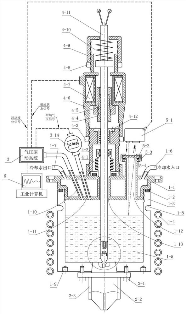
Melt flow control device and method for melt coating forming process
A flow control device and melt coating technology, applied in the direction of improvement of process efficiency, additive processing, energy efficiency, etc., can solve the problem of inability to respond quickly when the flow starts and stops, and achieve compact space layout of the device and reliable pressing force , the effect of convenient adjustment
- Summary
- Abstract
- Description
- Claims
- Application Information
AI Technical Summary
Problems solved by technology
Method used
Image

Examples
Embodiment Construction
[0051] The present invention will be described in detail below in conjunction with the accompanying drawings and specific embodiments.
[0052] In describing the present invention, it should be understood that the terms "center", "longitudinal", "transverse", "upper", "lower", "front", "rear", "left", "right", " The orientations or positional relationships indicated by "vertical", "horizontal", "top", "bottom", "inner" and "outer" are based on the orientations or positional relationships shown in the drawings, and are only for the convenience of describing the present invention and Simplified descriptions, rather than indicating or implying that the device or element referred to must have a particular orientation, be constructed and operate in a particular orientation, and thus should not be construed as limiting the invention. In addition, the terms "first" and "second" are used for descriptive purposes only, and cannot be interpreted as indicating or implying relative import...
PUM
 Abstract
Description
Claims
Application Information