Automatic pushing-in device for profile frame material

A frame material and profile technology, which is applied in the field of automatic push-in device for profile frame material, can solve the problems of time-consuming and laborious, unstable positioning, flawed cutting accuracy, etc., and achieve the effect of flexible adjustment range.

Pending Publication Date: 2021-07-09
TAICANG WEGOMA MACHINERY
View PDF7 Cites 0 Cited by
  • Summary
  • Abstract
  • Description
  • Claims
  • Application Information

AI Technical Summary

Problems solved by technology

There are various problems in the positioning and pushing cutting system of traditionally applied profiles. For example, the positioning of profiles is not accurate enough, the positioning is not stable, and it is prone to deflection during cutting, which affects the cutting effect. Many of them are caused by profile pushing or conveying methods. These technical problems are not only time-consuming and labor-intensive, but also have certain flaws in cutting accuracy.

Method used


Image

  • Automatic pushing-in device for profile frame material
  • Automatic pushing-in device for profile frame material
  • Automatic pushing-in device for profile frame material

Examples


Embodiment 1

[0056] An automatic push-in device for profile frame materials, combined with a three-axis servo drive power head, can read and identify the CAD data file of the profile cross-section through the control software, automatically calculate the clamping position of the manipulator, and control the automatic clamping of the manipulator clamp. Positioning clamps the profile.

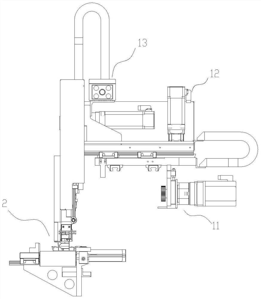
[0057] The three-axis power mechanism 1 includes an X-axis component 11 , a Y-axis component 12 and a Z-axis component 13 , and the X-axis component 11 is configured as an actuator component that provides an effective pushing displacement of the frame material. Specifically, the three-axis servo drive system composed of the X-axis assembly 11, the Y-axis assembly 12, and the Z-axis assembly 13, according to the instructions of the control system, the clamping part of the fully automatic pushing manipulator is positioned at the clamping position of the workpiece, And clamp the workpiece to realize the intellig...

Embodiment 2

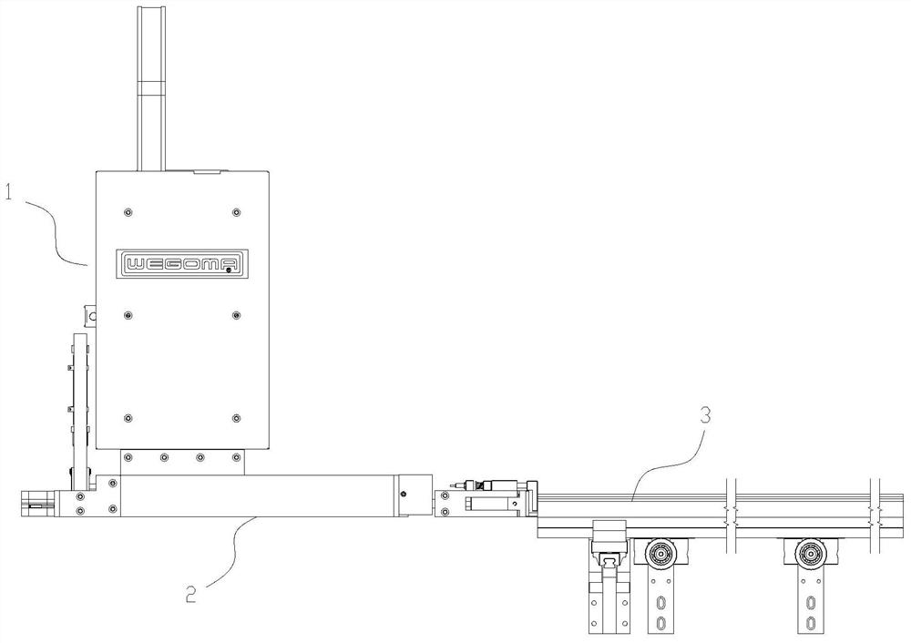
[0064] An automatic push-in device for profile frame material, driven by a three-axis power mechanism based on rectangular coordinates, clamped from the end of the frame material and pushed along the length direction of the frame material, the three-axis power mechanism 1 drives the pusher manipulator 2 to generate displacement and push The power of frame material. Through the X-axis assembly 11 , the Y-axis assembly 12 and the Z-axis assembly 13 , the rapid and precise positioning of the clamping position of the pushing manipulator 2 is realized. At the same time, the X-axis assembly 11 is responsible for effectively pushing the workpiece.

[0065] Specifically, the pushing manipulator 2 includes: a clamping part, a first component, a second component and an induction component.

[0066] The first component provides the driving force for the opening / closing action of the clamping part, while the second component provides the turning power of the clamping part. The sensing c...

Embodiment 3

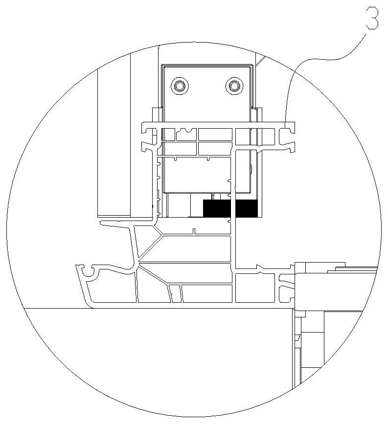
[0079] This embodiment is the application of a fully automatic material pushing manipulator on the door, window and curtain wall profile processing equipment, and the profile frame material automatic pushing device is used in combination with the material feeding line. The feeding line is a belt-type feeding structure, such as Figure 11 shown. The fully automatic feeding table includes a plurality of conveying belts 4, the frame material 3 (or profile) is placed in parallel on the conveying belts 4, and the conveying belts 4 feed materials along a single direction. At the end of the conveying belt 4 is a row of supporting guide rollers 5, and the frame material 3 is transported to the supporting guiding rollers 5 by the conveying belt 4. The profile frame material automatic push-in device is arranged at the end of the material guide roller 5, and the corresponding processing host is arranged at the end of the material guide roller 5, and the profile frame material automatic ...


PUM


Abstract

The invention discloses an automatic pushing-in device for a profile frame material, which is driven by a three-axis power mechanism based on rectangular coordinates, clamps the frame material from the end part of the frame material and pushes the frame material along the length direction of the frame material; the three-axis power mechanism drives a material pushing mechanical arm to generate displacement and power for pushing the frame material; the three-axis power mechanism comprises an X-axis assembly and a material pushing manipulator, the X-axis assembly is configured to be an execution assembly providing effective pushing displacement for the frame material; the material pushing manipulator is configured to be an executing mechanism for clamping the frame material and comprises a clamping part, a first assembly, a second assembly and a sensing assembly, wherein the clamping part comprises at least one movable clamping finger; the clamping part is used for clamping from the wall thickness part of the end surface of the frame material; the first assembly is configured to be an execution structure for driving the clamping part to be opened / closed; the second assembly is configured to be an execution structure for driving the clamping part to turn over in the pushing direction; the second assembly drives to enable the clamping part to turn over in a frame material placing direction after the clamping part clamps the frame material; and the sensing assembly is arranged on the clamping part so as to convert touch of the frame material on the sensing assembly into a displacement sensing signal and collect the displacement sensing signal.

Description

technical field [0001] The invention relates to the technical field of profile frame material processing equipment, in particular to an automatic profile frame material push-in device adapted to a photovoltaic frame material production line. Background technique [0002] In the production process of photovoltaic modules, the cells, glass, EVA film, and TPT backplane are bonded and fused together under certain temperature, pressure and vacuum conditions, and then framed, that is, the cells and the The glass components are fixed around to protect the cells and glass components. At the same time, profile frames are also commonly used in the door, window and curtain wall frame processing industry. [0003] Usually, the positioning and pushing of the profile frame material is used to cooperate with other processing procedures, for example, the sawing of the profile, etc. There are various problems in the positioning and pushing cutting system of traditionally applied profiles. ...

Claims


Application Information

Patent Timeline
IPC IPC(8): B23Q7/04B23Q7/06
CPCB23Q7/06B23Q7/04
Inventor 刘云华刘海涛
Owner TAICANG WEGOMA MACHINERY
Why Eureka
Try Eureka