
Shot blasting clearing device

Active Publication Date: 2021-07-09
SHANDONG KAITAI SHOT BLASTING MACHINERY
View PDF14 Cites 3 Cited by
  • Summary
  • Abstract
  • Description
  • Claims
  • Application Information

AI Technical Summary

Problems solved by technology

If the shot blasting separation structure is configured to the shot blasting cleaning device, it will inevitably have relatively high requirements for the layout of the equipment, that is, to use relatively few equipment to achieve a relatively complicated process, which is also contrary to the requirement of separate separation of projectiles.

Method used


Image

  • Shot blasting clearing device

Examples


Embodiment Construction

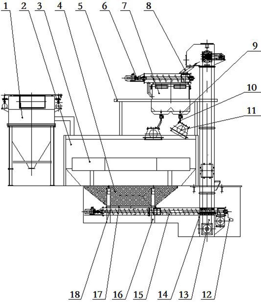
[0030] As a guideline for understanding the present invention, it should first be explained that, compared with traditional shot blasting devices, the shot blasting device according to the embodiment of the present invention has approximately the same composition, that is, both include a shot blasting chamber 2, and are installed in a shot blasting device. The shot blasting device 11 on the shot chamber 2, the collecting hopper 4 for collecting shot slag, the screw conveyor 18 for horizontally conveying the materials collected by the collecting hopper 4, and the vertical lifting of the materials conveyed by the screw conveyor 18 to a given level. The hoist 13 with the highest height, and the pellet separator 7 that separates the pellets and slag from the feed material of the hoist 13. Relatively speaking, in the embodiment of the present invention, the local structure of the above composition is improved, and an overflow hopper 12 is added. Correspondingly, the discharge port a...


PUM


Abstract

The invention discloses a shot blasting clearing device. The shot blasting clearing device comprises a shot blasting chamber, a shot blasting device, a workbench, a spiral conveyer, a material overflowing hopper, an elevator and a shot-slag separator, wherein the hopper wall of a material receiving hopper matching with the shot blasting chamber and used for collecting shot slag is a screen so as to screen the shot slag with the particle size larger than or equal to that of the shot slag, the shot blasting device is installed on the shot blasting chamber, the workbench is installed in the shot blasting chamber, the spiral conveyer is positioned below the shot blasting chamber and is used for receiving the shot slag collected by the material receiving hopper and conveying the shot slag to a given side of the shot blasting chamber; the screen drum is arranged at the tail end of a pipe shell of the spiral conveyor and is used for screening shots and slag materials meeting the shot particle size range; the material overflowing hopper is installed at the tail end of a screen drum so as to guide out residues screened by the screen drum, the elevator is located on the given side of the shot blasting chamber so as to receive the shot slag screened by the screen drum and lift the shot slag to a given height, and the shot-slag separator is used for receiving the shot slag conveyed by the elevator so as to carry out shot-slag separation and conveying the separated shot slag to the shot blasting device. According to the shot blasting clearing device, the structure is relatively compact, so that shots can be effectively recycled.

Description

technical field [0001] The invention relates to a shot blasting cleaning device. Background technique [0002] Some relatively large workpieces, such as the crankshaft of a ship, are relatively large in size. When continuous shot blasting is performed on them, the cycle of one shot blasting process is often relatively long, and a large number of projectiles are bound to be required. For the shot blasting of these large workpieces, the required projectiles often need to be recycled, otherwise the supply of projectiles and the follow-up treatment of projectiles falling in the working area will be a relatively big problem. [0003] Chinese patent document CN105922141A discloses a turntable shot blasting machine, which includes a shot blasting machine chamber body, a lifting mechanism, a shot-sand separation structure, and a turntable driven by a drive mechanism. Workpieces are placed on the turntable and scattered during shot blasting. The shot material in the shot blasting ma...

Claims


Application Information

Patent Timeline
IPC IPC(8): B24C1/08B24C3/24B24C7/00B24C9/00
CPCB24C1/08B24C3/24B24C9/006B24C7/0092Y02P70/10
Inventor 王守仁王瑞国李计良冯承亮李建亮孙新凯喻美
Owner SHANDONG KAITAI SHOT BLASTING MACHINERY
Learn More