
Extruder and 3D printing equipment

A technology of extruder and discharge nozzle, which is applied in the field of 3D printing, can solve the problems of difficult control of extruder speed, large size of transmission mechanism, and low printing accuracy, and achieve easy control, lower overall quality, and fast response Effect

Pending Publication Date: 2021-07-09
SHENZHEN ANYCUBIC TECH CO LTD
View PDF0 Cites 0 Cited by
  • Summary
  • Abstract
  • Description
  • Claims
  • Application Information

AI Technical Summary

Problems solved by technology

In order to increase the reduction ratio of the transmission mechanism to further reduce the motor torque, the transmission mechanism is usually large in size and heavy in weight, resulting in large inertia of the extruder, making it difficult to control the speed of the extruder, thereby improving the printing accuracy during 3D printing. not tall
It can be seen that the printing accuracy of the existing 3D printing equipment is not high

Method used


Image

  • Extruder and 3D printing equipment
  • Extruder and 3D printing equipment
  • Extruder and 3D printing equipment

Examples


Embodiment Construction

[0035] The following will clearly and completely describe the technical solutions in the embodiments of the present application with reference to the drawings in the embodiments of the present application. Obviously, the described embodiments are part of the embodiments of the present application, not all of them. In the case of no conflict, the following embodiments and features in the embodiments can be combined with each other. In addition, based on the embodiments in the present application, all other embodiments obtained by persons of ordinary skill in the art without creative efforts fall within the protection scope of the present application.

[0036] The terms "first", "second" and the like in the specification and claims of the present application are used to distinguish similar objects, and are not used to describe a specific sequence or sequence. It should be understood that the terms so used are interchangeable under appropriate circumstances such that the embodime...


PUM


Abstract

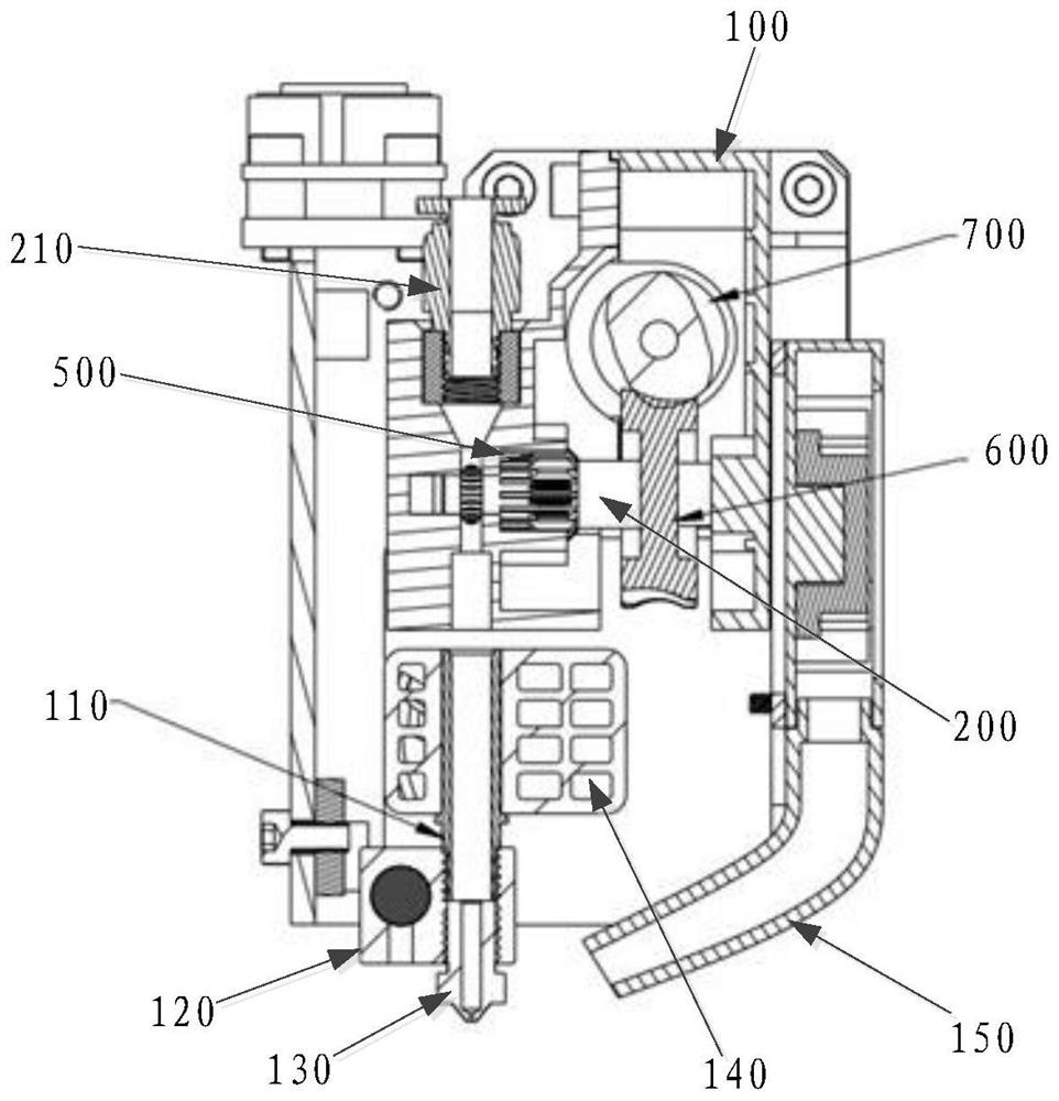
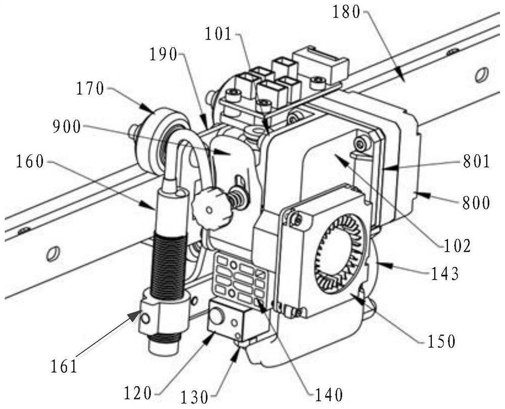
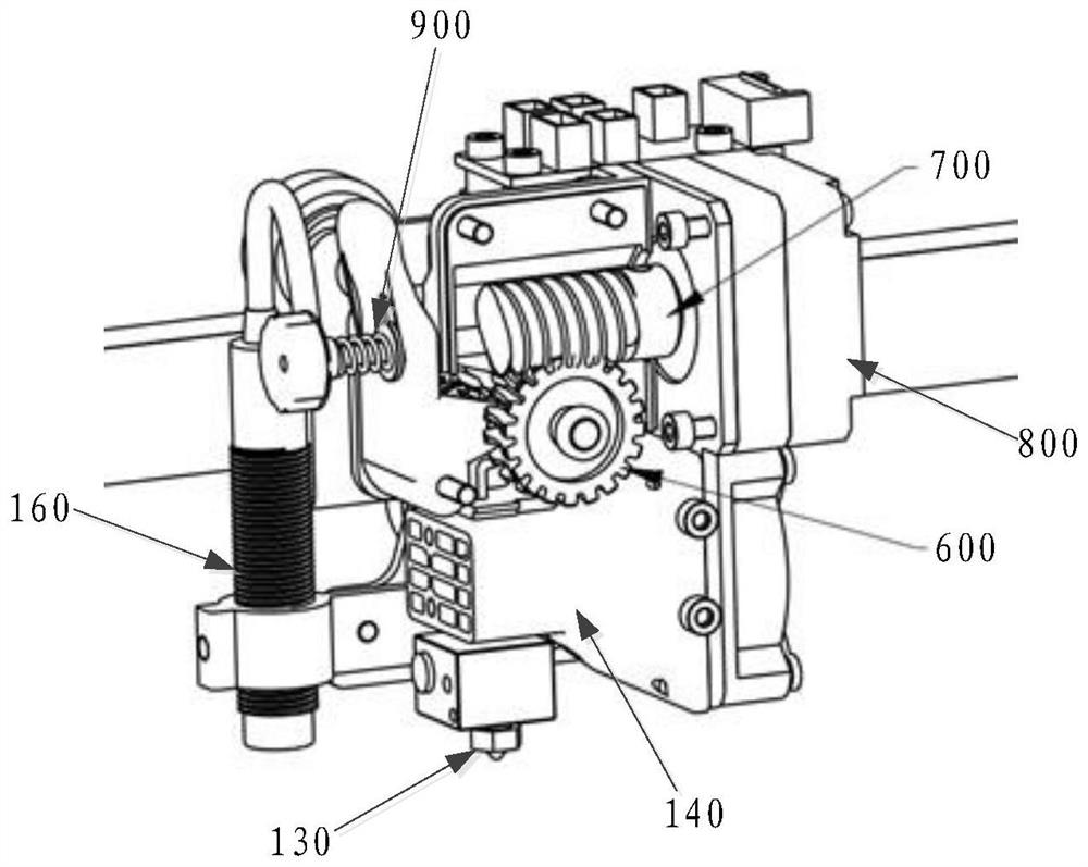
The invention discloses an extruder and 3D printing equipment. The extruder comprises a shell, a first shaft, a second shaft, a first roller, a second roller, a worm gear, a worm and a driving part. The first shaft and the second shaft are respectively arranged in the shell, and the first shaft is parallel to the second shaft. The first roller sleeves the first shaft, the second roller sleeves the second shaft, the circumferential surface of the first roller is opposite to the circumferential surface of the second roller, and a gap for materials to pass through is formed between the first roller and the second roller. The output end of the driving part is connected with the worm, the worm gear is arranged on the first shaft in a sleeving mode, the worm is connected with the worm gear in a meshed mode, and the driving part is used for driving the first shaft to rotate when driving the worm to rotate. If the driving part drives the first shaft to rotate, the first roller rotates along with the first shaft so as to extrude and push the materials in the gap to move. The 3D printing equipment comprises the extruder. According to the scheme, the printing precision of the 3D printing equipment using the extruder can be improved.

Description

technical field [0001] This application relates to the technical field of 3D printing, in particular to an extruder and 3D printing equipment. Background technique [0002] 3D printing equipment, also known as 3D printing equipment (3Dimension Printer, 3DP), is a kind of accumulative manufacturing technology, that is, a kind of equipment of rapid prototyping technology. It is based on a digital model file, using special wax, powdered metal or Adhesive materials such as plastics are used to create three-dimensional objects by sequentially printing multiple layers of adhesive materials. [0003] In the 3D printing equipment, the extruder is an important part of the 3D printing equipment, and an extruding mechanism is arranged inside it to deliver materials to the nozzle of the extruder. In order to squeeze the material entering the extruder and reduce the torque of the motor, the extruder usually needs to use a transmission mechanism. In order to increase the reduction ratio...

Claims


Application Information

Patent Timeline
IPC IPC(8): B29C64/20B29C64/295B29C64/321B29C64/241B29C35/16B33Y30/00B33Y40/00
CPCB29C35/16B29C2035/1666B33Y30/00B33Y40/00B29C64/20B29C64/241B29C64/295B29C64/321
Inventor 贺坤
Owner SHENZHEN ANYCUBIC TECH CO LTD
Learn More