
Electric driving hydraulic device, braking system and automobile

A hydraulic device and electric drive technology, which is applied in the direction of brake safety system, brake transmission device, brake, etc., can solve the problem of pressure waste of oil pressure accumulator, and achieve the effect of ensuring safety

Active Publication Date: 2021-07-09
BYD CO LTD
View PDF6 Cites 2 Cited by
  • Summary
  • Abstract
  • Description
  • Claims
  • Application Information

AI Technical Summary

Problems solved by technology

[0007] The technical problem to be solved by the present invention is: aiming at the problem that the existing electric drive hydraulic device cannot provide boost for the braking system when the motor fails or the system enters the standby mode, resulting in a waste of pressure in the oil pressure accumulator, provide a Electric drive hydraulic device, braking system and automobile

Method used


Image

  • Electric driving hydraulic device, braking system and automobile
  • Electric driving hydraulic device, braking system and automobile
  • Electric driving hydraulic device, braking system and automobile

Examples


no. 1 example

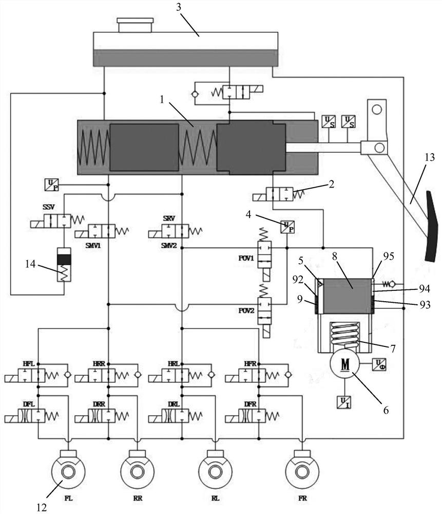
[0049] Such as Figure 1 to Figure 4 As shown, the brake system provided by the first embodiment of the present invention includes a master cylinder 1 , a master cylinder solenoid valve 2 , a liquid storage pot 3 , a controller, a pressure sensor 4 and an electric drive hydraulic device 6 .

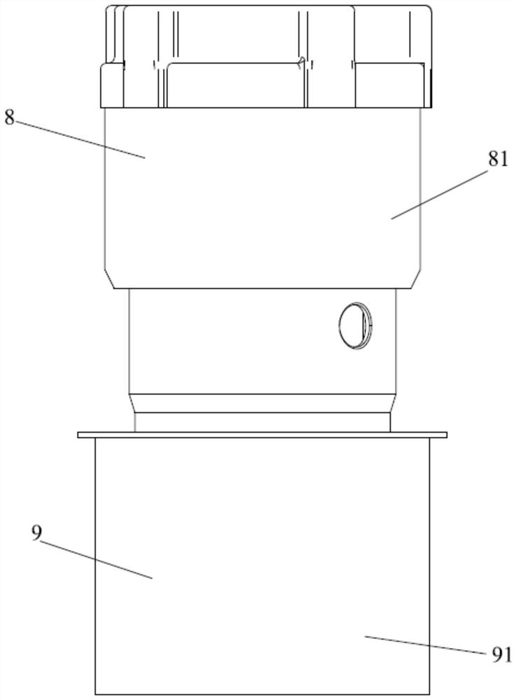
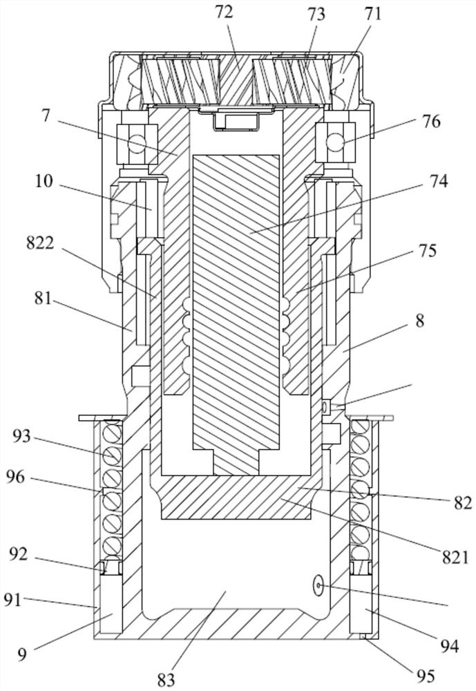
[0050] The electric drive hydraulic device includes a motor 6 , a transmission device 7 , a piston pump 8 and a hydraulic accumulator 9 . The piston pump 8 includes a piston pump housing 81 and a piston pump piston 82. A piston pump chamber 83 is formed in the piston pump housing 81. The hydraulic accumulator 9 includes a hydraulic accumulator housing 91, a hydraulic accumulator Energizer piston 92 and elastic member 93, the hydraulic accumulator housing 91 is fixed or integrally formed on the first end of the piston pump housing 81, the hydraulic accumulator housing 91 and the piston pump A hydraulic accumulator chamber 94 is formed between the first ends of the housing 81 , and a flow ...

no. 2 example

[0079] Figure 5 Shown is a schematic diagram of the braking system provided by the second embodiment of the present invention.

[0080] The difference from the first embodiment is:

[0081] The piston pump housing 81 is provided with a piston pump oil port 85, a piston pump solenoid valve 15 is connected between the piston pump oil port 85 and the master cylinder solenoid valve 2, and the hydraulic accumulator liquid outlet A hydraulic accumulator solenoid valve 16 is connected between 95 and the master cylinder solenoid valve 2 .

[0082] In addition to the pressure sensor 4 of the traditional braking system, another pressure sensor 17 is added, and the added pressure sensor 17 is arranged on a separate pipeline connected to the fluid outlet 95 of the hydraulic accumulator.

[0083] In this way, there are two oil paths in the piston pump chamber 83 , and one oil path is: piston pump chamber 83 - piston pump solenoid valve 15 - second solenoid valve - brake wheel cylinder 1...

no. 3 example

[0086] In addition, the third embodiment of the present invention provides an automobile, which includes the electric drive hydraulic device of the above embodiment or the brake system of the above embodiment.

[0087] Preferably, the car is a fully automatic intelligent driving car (unmanned car). The braking system can perform braking according to the driver's braking request (such as stepping on the brake pedal), or can perform fully automatic braking according to signals collected by external sensors, cameras and other equipment.


PUM


Abstract

The invention relates to an electric drive hydraulic device, a braking system and an automobile. The electric drive hydraulic device comprises a motor, a transmission device, a piston pump and a hydraulic energy accumulator. The piston pump comprises a piston pump shell and a piston pump piston, a piston pump cavity is formed in the piston pump shell, the hydraulic energy accumulator comprises a hydraulic energy accumulator shell, a hydraulic energy accumulator piston and an elastic piece, and a hydraulic energy accumulator cavity is formed between the hydraulic energy accumulator shell and the first end of the piston pump shell. A flow channel is arranged in the piston pump shell, and a one-way valve is arranged in the flow channel. The motor drives a piston of the piston pump to move in the axial direction of the piston pump through the transmission device, so that brake fluid in a cavity of the piston pump can enter a cavity of the hydraulic energy accumulator through the one-way valve, and the piston of the hydraulic energy accumulator is pushed to compress the elastic piece. According to the electric driving hydraulic device and the braking system, hydraulic pressure in the hydraulic energy accumulator can be stored for a long time.

Description

technical field [0001] The invention belongs to the technical field of automobile braking, and in particular relates to an electric drive hydraulic device, a braking system and an automobile. Background technique [0002] The Chinese patent application with the publication number CN109305154A discloses a kind of electric drive hydraulic device, including a motor, a booster cylinder and an oil pressure accumulator. The outlet of the oil pressure accumulator is provided with an accumulator electromagnetic valve, and the electromagnetic The valve controls the oil pressure accumulator to supply oil to the brake system. The motor is connected to the booster cylinder through the transmission mechanism. The outlet of the booster cylinder is connected to the solenoid valve of the booster cylinder. The booster cylinder is driven to output hydraulic pressure to charge the accumulator. [0003] The above-mentioned electrically driven hydraulic device has the following deficiencies: ...

Claims


Application Information

Patent Timeline
Patent Type & Authority Applications(China)
IPC IPC(8): B60T17/22B60T13/74
CPCB60T17/22B60T13/745
Inventor 程佳朱晓军郭海
Owner BYD CO LTD
Learn More