Health monitoring equipment for hot water energy storage tank
A technology of health monitoring and energy storage tank, which is applied in the measurement, container, packaging and other directions by measuring the frequency change force of the stressed vibrating element, which can solve the problems of unification and achieve the effect of ensuring safe operation and early warning of damage
- Summary
- Abstract
- Description
- Claims
- Application Information
AI Technical Summary
Problems solved by technology
Method used
Image

Examples
Embodiment Construction
[0023] Embodiments of the invention are described in detail below, examples of which are illustrated in the accompanying drawings. The embodiments described below by referring to the figures are exemplary and are intended to explain the present invention and should not be construed as limiting the present invention.
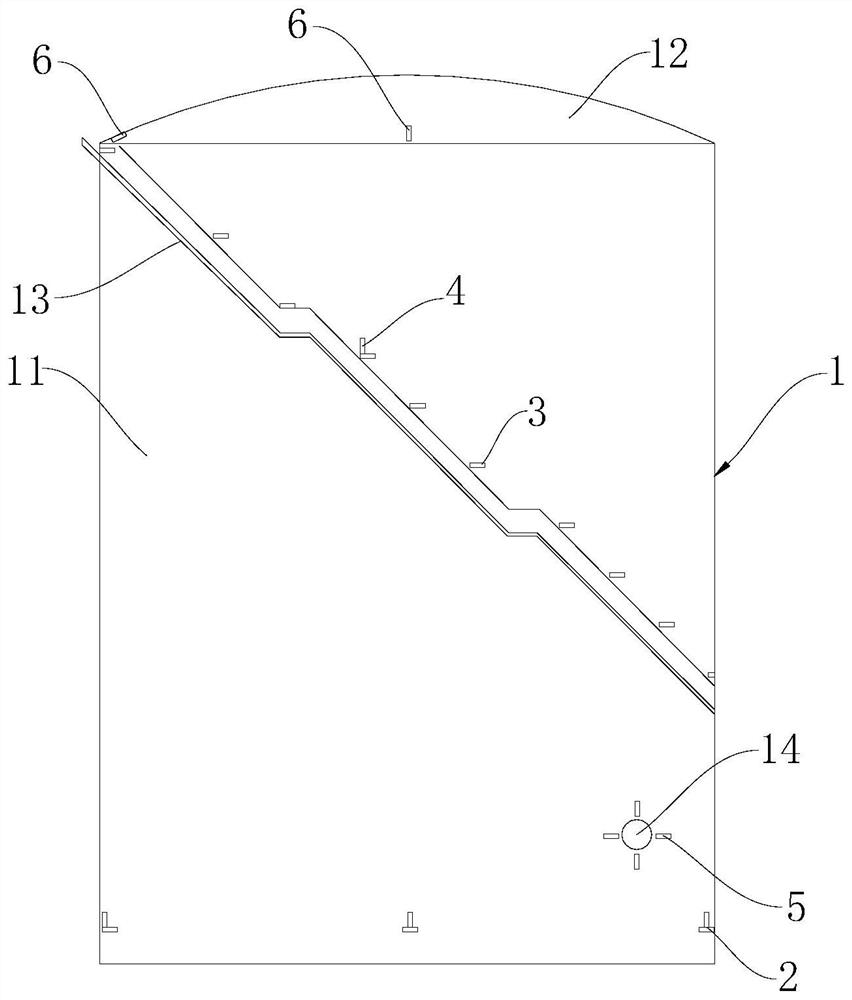
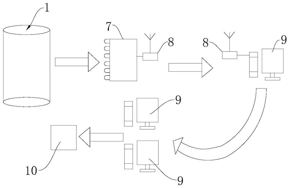
[0024] Combine below figure 1 and figure 2 A hot water storage tank health monitoring device according to an embodiment of the present invention is described.
[0025] The hot water energy storage tank health monitoring device according to the embodiment of the present invention includes a hot water energy storage tank 1 , a vibrating wire sensor and a data acquisition instrument 7 . There are multiple vibrating wire sensors, and the multiple vibrating wire sensors are fixed on the outer surface of the hot water energy storage tank 1 . Each of the plurality of vibrating wire sensors is connected to a data acquisition instrument 7 .
[0026] Specifically, the...
PUM
 Abstract
Description
Claims
Application Information
PatSnap Eureka turns technology decisions into work you can execute. Powered by our Innovation Knowledge Graph, it runs expert workflows across engineering, life sciences, materials and intellectual property. Get your review-ready output in minutes.


