
A kind of carbon fiber modification method and product thereof

A carbon fiber modification technology, which is applied in the field of carbon fiber modification methods and its products, can solve the problems of carbon fiber mechanical properties, poor toughness, etc.

Active Publication Date: 2022-03-29
ANHUI POLYTECHNIC UNIV +1
View PDF6 Cites 0 Cited by
  • Summary
  • Abstract
  • Description
  • Claims
  • Application Information

AI Technical Summary

Problems solved by technology

[0002] Carbon fiber is a fiber structure of inorganic carbon materials. It is a microcrystalline graphite material obtained by carbonization and graphitization of inorganic carbon materials. Carbonization and graphitization in the manufacturing process of carbon fibers endow carbon fibers with many excellent properties. High strength and high modulus, good electrical and thermal conductivity, good electromagnetic shielding, good fatigue resistance, is a new generation of reinforced fibers; but carbon fiber itself is a brittle material with poor toughness; in addition, some defects will occur on the surface of the fiber during the preparation process. The mechanical properties are affected during use, so carbon fiber is rarely used alone as a structural material, and is often used as a reinforcing material in combination with other materials

Method used


Image

  • A kind of carbon fiber modification method and product thereof
  • A kind of carbon fiber modification method and product thereof
  • A kind of carbon fiber modification method and product thereof

Examples


Embodiment 1

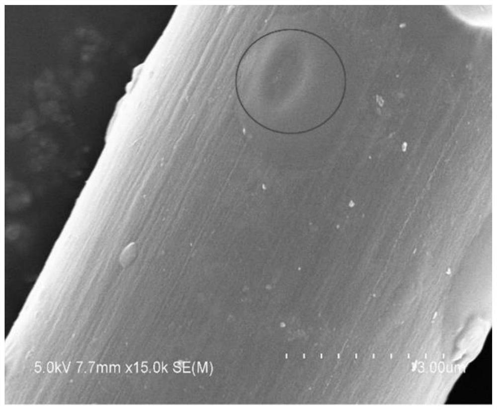
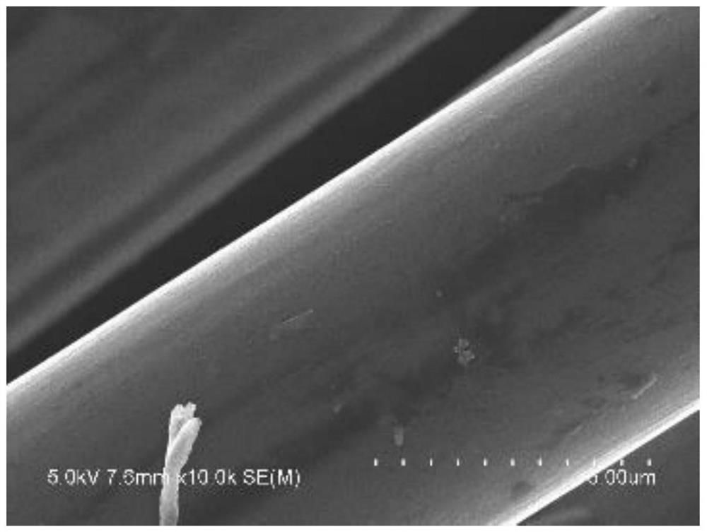
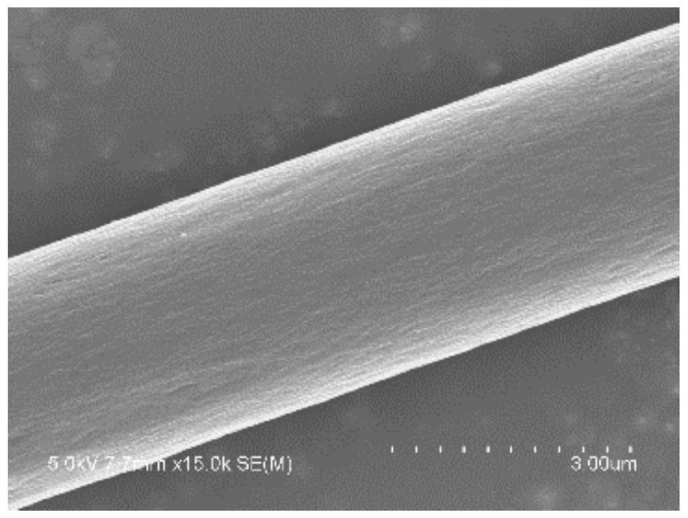
[0029] (1) Place the bundled 12K carbon fibers produced by Toray in Japan in an acetone solution at a constant temperature of 70°C for 24 hours, then wash them alternately with absolute ethanol and deionized water to remove the sizing agent, dust and oil on the surface of the fibers, and then Dry and cool at 80°C for 24 hours;

[0030] (2) Use the carbon fiber treated in step (1) as the substrate, fix it on the cardboard in parallel, install the carbon target on the cathode plate, place the substrate under the substrate support, and perform magnetron sputtering under the following conditions Processing: sputtering power 250W, magnetron sputtering pressure 1Pa, sputtering time 30min, background vacuum 2×10 -3 Pa, the distance between the target and the substrate is 4 cm, high-purity argon (99.999%) is used as the working gas, the flow rate of the argon gas is 80 ml / min, and the substrate holder rotates at a speed of 30 r / min.

[0031] (3) The carbon fiber treated in step (2) i...

Embodiment 2

[0039] Same as Example 1, the difference is that the sputtering power is 250W, the magnetron sputtering pressure is 1Pa, the sputtering time is 45min, and finally it is treated in a vacuum furnace at 200°C for 40min. The tensile breaking strength of the treated bundled carbon fiber is 0.8956KN.

Embodiment 3

[0041] Same as Example 1, the difference is that under the condition of 250W, the magnetron sputtering pressure is 1Pa, the sputtering time is 45min, and the heat treatment condition is 300°C for 40min. The tensile breaking strength of the treated bundled carbon fiber is 0.8533KN.


PUM


Abstract

The invention relates to the technical field of modified carbon fibers, in particular to a carbon fiber modification method and its products; modified carbon fibers are obtained by heating the carbon fibers in an inert atmosphere after magnetron sputtering treatment; wherein the magnetron sputtering treatment takes carbon fibers as the Substrate, with carbon as the target, sputtering conditions: vacuum degree 2×10 ‑3 Pa, the target base distance is 4cm, the magnetron sputtering power is 150-350W, the magnetron sputtering pressure is 0.5-1.6Pa, the magnetron sputtering time is 20-60min, high-purity argon is used as the working gas, and the argon flow rate is 80ml / min; heat treatment conditions: heating rate 5°C / min, heat treatment temperature 200-600°C, heat treatment time 25-40min; the carbon fiber modified by the present invention can increase the tensile breaking strength by 4%-12%. The tensile work can be increased by 15%‑40%, which can effectively improve the mechanical properties of carbon fibers.

Description

technical field [0001] The invention relates to the technical field of carbon fiber modification, in particular to a carbon fiber modification method and a product thereof. Background technique [0002] Carbon fiber is a fiber structure of inorganic carbon materials. It is a microcrystalline graphite material obtained by carbonization and graphitization of inorganic carbon materials. Carbonization and graphitization in the manufacturing process of carbon fibers endow carbon fibers with many excellent properties. High strength and high modulus, good electrical and thermal conductivity, good electromagnetic shielding, good fatigue resistance, is a new generation of reinforced fibers; but carbon fiber itself is a brittle material with poor toughness; in addition, some defects will occur on the surface of the fiber during the preparation process. The mechanical properties are affected during use, so carbon fiber is rarely used alone as a structural material, and is often used as...

Claims


Application Information

Patent Timeline
Patent Type & Authority Patents(China)
IPC IPC(8): C23C14/35C23C14/06D06M11/74D06M101/40
CPCC23C14/35C23C14/0605D06M11/74D06M2101/40C23C14/021C23C14/541D06M10/006C23C14/024C23C14/5806
Inventor 杨莉徐珍珍倪庆清陈缘
Owner ANHUI POLYTECHNIC UNIV
Learn More