

Automatic treatment device for collecting and recycling rainwater
A treatment device and rainwater collection technology, which is applied in water supply devices, drinking water devices, water/sewage treatment, etc., can solve the problems of rainwater collection process being easy to be mixed with debris, unable to discharge rainwater, and damage crops, etc., to improve the fixing effect , convenient collection and storage, and the effect of improving purification intensity
- Summary
- Abstract
- Description
- Claims
- Application Information
AI Technical Summary
Problems solved by technology
Method used
Image

Examples
Embodiment Construction
[0036] The embodiments of the present invention will be described in detail below with reference to the accompanying drawings, but the present invention can be implemented in many different ways defined and covered by the claims.
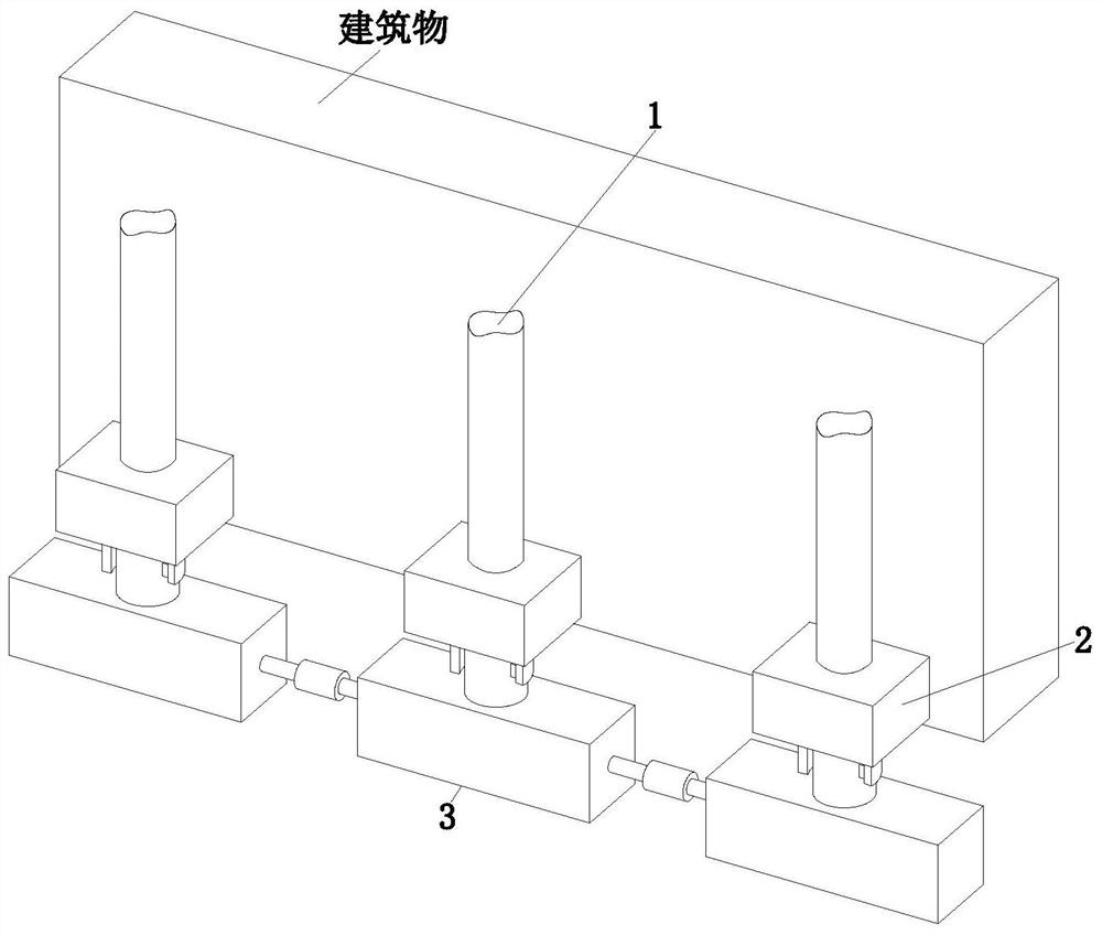
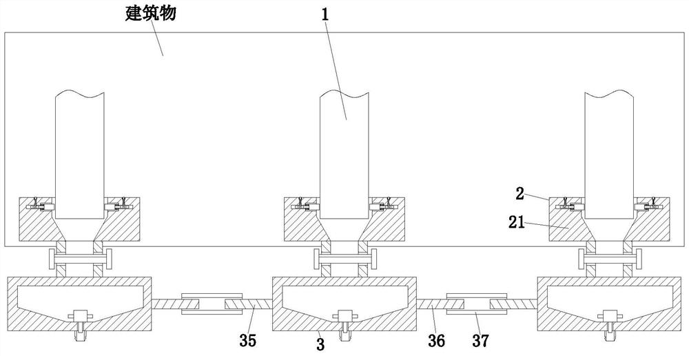
[0037] Such as Figure 1 to Figure 12 The shown automatic rainwater collection and reuse processing device includes a drainpipe 1, a connecting unit 2 and a filtering unit 3. The drainpipe 1 is installed at the drain of a building, and the lower end of the drainpipe 1 is provided with a connecting unit 2 , a filter unit 3 is provided along the lower end of the connection unit 2, wherein:
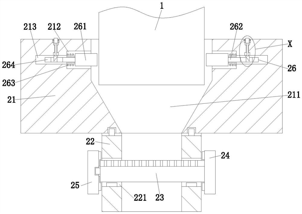
[0038]The connecting unit 2 includes a support ring 21, a connecting pipe 22, a filter screen 23, a No. 1 arc plate 24, a No. 2 arc plate 25 and a fixing assembly 26, wherein: the support ring 21 is sleeved on the lower end of the drain pipe 1 On the outer wall, a water inlet 211 connected to the drain pipe 1 is provided along the lower end of the inner side wall...
PUM
 Abstract
Description
Claims
Application Information