
A Design Method for Prefabricated Concrete and Its Joint Interface in Common Environment

A general environment, concrete technology, applied in design optimization/simulation, architecture, geometric CAD, etc., can solve problems such as reducing the alkaline environment of concrete, causing corrosion, affecting the structural performance, etc., to improve durability and prolong durability. effect of age

Active Publication Date: 2022-05-17
GUANGDONG POWER GRID CO LTD
View PDF0 Cites 0 Cited by
  • Summary
  • Abstract
  • Description
  • Claims
  • Application Information

AI Technical Summary

Problems solved by technology

The material properties and hydration degrees of different concrete matrices near the interface layer are different, and there is a deformation coordination problem in the interface layer. Under the action of load and shrinkage, it is easy to form weak links; on the other hand, these weak interface layers provide convenient transmission for harmful substances The method accelerates the corrosion of interfacial reinforcement, and the volume expansion of corrosion products will aggravate the damage of the bonding interface, resulting in reduced durability or even failure of the structure near the bonding interface.
The failure cases caused by the insufficient durability of the concrete bonding interface are not uncommon, seriously affecting the applicable performance of the structure, and threatening the safe service of the structure
[0003] In the general atmospheric environment, the interface of prefabricated concrete is easily eroded by carbon dioxide, which reduces the alkaline environment inside the concrete, which leads to the bluntness and corrosion of steel bars, seriously affects the durability of concrete structures, and even endangers the safe service of structures.

Method used


Image

  • A Design Method for Prefabricated Concrete and Its Joint Interface in Common Environment
  • A Design Method for Prefabricated Concrete and Its Joint Interface in Common Environment
  • A Design Method for Prefabricated Concrete and Its Joint Interface in Common Environment

Examples


Embodiment Construction

[0052] The following will clearly and completely describe the technical solutions in the embodiments of the present invention with reference to the accompanying drawings in the embodiments of the present invention. Obviously, the described embodiments are only some, not all, embodiments of the present invention. Based on the embodiments of the present invention, all other embodiments obtained by persons of ordinary skill in the art without creative efforts fall within the protection scope of the present invention.

[0053] It should be understood that the step numbers used herein are only for convenience of description, and are not intended to limit the execution order of the steps.

[0054]It should be understood that the terminology used in the description of the present invention is for the purpose of describing particular embodiments only and is not intended to limit the present invention. As used in this specification and the appended claims, the singular forms "a", "an" ...


PUM


Abstract

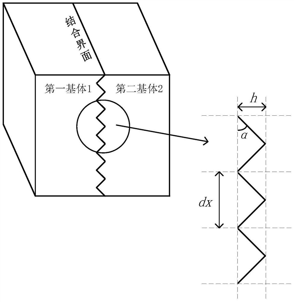
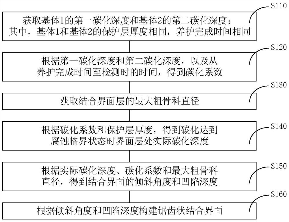
The invention discloses a prefabricated concrete under the action of ordinary environments and a method for designing a joint interface thereof, and relates to the technical field of prefabricated buildings. The method includes: obtaining the carbonization coefficient according to the first carbonization depth of the first base body and the second carbonization depth of the second base body, and the time from the completion time of the curing to the detection time; obtaining the maximum coarse aggregate of the bonding interface layer Diameter; according to the carbonization coefficient and the thickness of the protective layer, the actual carbonization depth at the interface layer is obtained when the carbonization reaches the corrosion critical state; according to the actual carbonization depth, carbonization coefficient and the maximum coarse aggregate diameter, the angle and height of the sawtooth of the zigzag joint interface are obtained; According to the angle and the height, a jagged bond interface is constructed. The invention quantifies and determines the carbonization coefficient of the concrete bonding interface and the roughness parameter of the concrete bonding interface, and can significantly prolong the durability service life of the assembled concrete structure.

Description

technical field [0001] The invention relates to the technical field of prefabricated buildings, in particular to a method for designing prefabricated concrete and its joint interface in common environments. Background technique [0002] Concrete bonding interfaces widely exist in concrete structures, such as structural joints such as construction joints, settlement joints, and expansion joints during concrete pouring, splicing joints during wet installation of prefabricated components, and joints between old and new concrete in structural repair and reinforcement. Wait. The concrete bonding interface is composed of different concrete matrix, interface layer and interface reinforcement. The material properties and hydration degrees of different concrete matrices near the interface layer are different, and there is a deformation coordination problem in the interface layer. Under the action of load and shrinkage, it is easy to form weak links; on the other hand, these weak int...

Claims


Application Information

Patent Timeline
Patent Type & Authority Patents(China)
IPC IPC(8): E04B1/16G06F30/13G06F30/20
CPCE04B1/16G06F30/13G06F30/20
Inventor 吴小蕙张章亮王彦峰王流火陈辉祥夏晋王洁车伟娴李嘉杰陈锟郭金根朱文卫梁爱武刘明
Owner GUANGDONG POWER GRID CO LTD
Learn More