
Power distribution network prediction auxiliary device and prediction state estimation method thereof

An auxiliary device and state estimation technology, which is applied in circuit devices, prediction, calculation, etc., can solve the problems of stationary and moving prediction auxiliary devices, large memory usage of orthogonal transformation algorithm, and weak robustness of least squares algorithm. , to facilitate predictable operation, improve stability, and avoid collisions

Pending Publication Date: 2021-07-09
INST OF ECONOMIC & TECH STATE GRID HEBEI ELECTRIC POWER +2
View PDF6 Cites 0 Cited by
  • Summary
  • Abstract
  • Description
  • Claims
  • Application Information

AI Technical Summary

Problems solved by technology

[0006] The invention provides a distribution network prediction auxiliary device and its prediction state estimation method, which solves the problems of domestic and foreign research on distribution network state estimation. The distribution network state estimation algorithm includes least square algorithm, fast decomposition algorithm, normal The alternating transformation algorithm, the measurement transformation state estimation algorithm, the least squares algorithm has the problem of weak tolerance to errors, the fast decomposition algorithm has the problem of large errors, the orthogonal transformation algorithm has the problem of large memory usage, and the measurement transformation state estimation algorithm The problem is that the efficiency is low, and the existing prediction auxiliary device cannot be statically fixed and moved according to the actual needs of the user during use

Method used


Image

  • Power distribution network prediction auxiliary device and prediction state estimation method thereof
  • Power distribution network prediction auxiliary device and prediction state estimation method thereof
  • Power distribution network prediction auxiliary device and prediction state estimation method thereof

Examples


Embodiment Construction

[0093] The present invention will be further described below in conjunction with the accompanying drawings and embodiments.

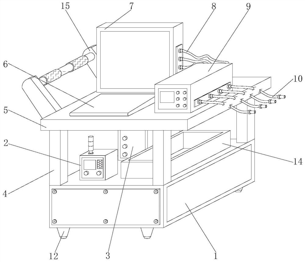
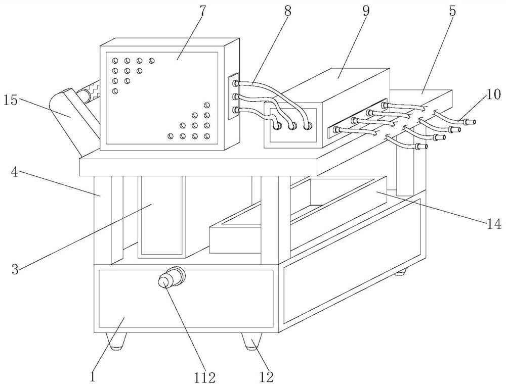
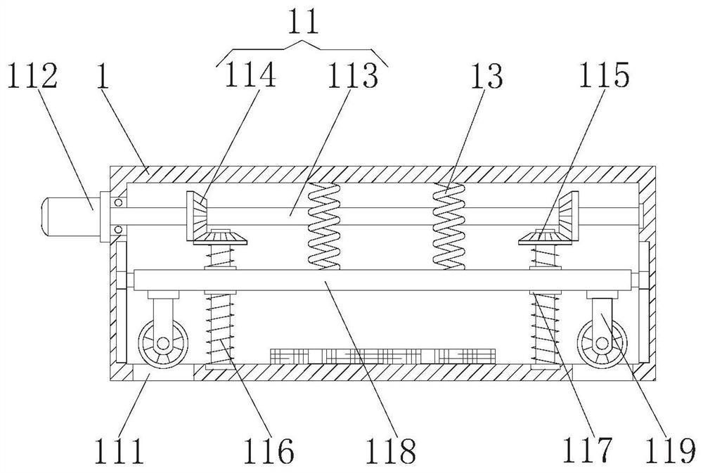
[0094] Please refer to figure 1 , figure 2 , image 3 , Figure 4 , Figure 5 , Figure 6 , Figure 7 , Figure 8 and Figure 9 ,in figure 1 A structural schematic diagram of a preferred embodiment of the distribution network prediction auxiliary device and its prediction state estimation method provided by the present invention; figure 2 for figure 1 The rear view of the structure of the distribution network forecasting auxiliary device and its forecasting state estimation method shown; image 3 for figure 1 Structural sectional view of the shown box; Figure 4 for figure 1 The update cycle relationship diagram of RTU and μPMU data of the distribution network prediction auxiliary device and its prediction state estimation method shown; Figure 5 for figure 1Schematic diagram of the data mixing preprocessing of the distribution netw...


PUM


Abstract

The invention provides a power distribution network prediction auxiliary device and a prediction state estimation method thereof. The device comprises a box body, wherein a controller is in bolting connection with the front face of the left side of the top of the box body, a host is in bolting connection with the back face of the left side of the top of the box body, supporting columns are in bolting connection with the periphery of the top of the box body, and a detection table is in bolting connection with the tops of the supporting columns; a keyboard is placed on the front side of the left side of the top of the detection table, a display is bolted to the back side of the left side of the top of the detection table, and connecting wires are sequentially inserted into the bottom of the right side of the display from top to bottom. Through cooperation of a through groove, a servo motor, a rotating rod, a driving gear, a driven gear, a lead screw, a threaded sleeve, a moving seat and universal wheels, the box body can be moved and fixed in a standing mode according to actual requirements of a user on site; therefore, the user can conveniently and rapidly conduct prediction operation on power distribution network equipment, the prediction efficiency of a power distribution network is improved, and long-time work waiting of the power distribution network is avoided.

Description

technical field [0001] The invention relates to the field of distribution network state estimation methods, in particular to a distribution network prediction auxiliary device and a prediction state estimation method thereof. Background technique [0002] In modern power grids, distribution network state estimation generally uses node voltage, branch current, and branch power as state variables to carry out distribution network state estimation algorithms, and data collection is obtained by real-time measurement by SCADA systems. RTU equipment monitors and collects steady-state parameters such as current effective value, active power, reactive power, and power factor, and has been widely used in dispatching automation systems. μPMU can collect voltage and current phasors in real time, and it is expected to be deployed on a large scale in the distribution network in the future and realize wide-area protection. The μPMU and the RTU data acquisition application system are inde...

Claims


Application Information

Patent Timeline
Patent Type & Authority Applications(China)
IPC IPC(8): G06Q10/04G06Q50/06G06F17/11G06F17/16G06F17/18H02J3/00H02J13/00F16M11/42
CPCG06Q10/04G06Q50/06G06F17/11G06F17/16G06F17/18H02J3/00H02J13/00001H02J13/00002H02J13/00004F16M11/42H02J2203/20H02J2203/10
Inventor 王涛容春艳柴林杰高立坡康伟任志刚李军阔郭佳申永鹏李光毅唐帅郝军魁林榕王中亮孙乾李江
Owner INST OF ECONOMIC & TECH STATE GRID HEBEI ELECTRIC POWER
Learn More