
Dual-frequency dual-circularly-polarized microstrip antenna

A dual circularly polarized, microstrip antenna technology, applied to antennas, antenna grounding devices, and devices that make the antenna work in different bands at the same time, can solve the problem of changing the input impedance characteristics of the antenna, high requirements for adhesive materials, and reducing the efficiency of the antenna and other problems, to achieve the effect of stable pattern, reducing interference and simple structure

Active Publication Date: 2021-07-09
GUANGDONG UNIV OF TECH
View PDF9 Cites 0 Cited by
  • Summary
  • Abstract
  • Description
  • Claims
  • Application Information

AI Technical Summary

Problems solved by technology

The patent adopts the upper radiation patch, the upper dielectric, the upper ground layer, the lower radiation patch, the lower dielectric and the lower ground layer from top to bottom to form the upper antenna and the lower antenna. , the gap between the media will significantly change the input impedance characteristics of the antenna, especially at high frequencies, the impedance characteristics of the gap are large, and the requirements for the bonding material between the stacks are high. If the bonding material is lossy and located next to a narrow slot, it will reduce the efficiency of the antenna

Method used


Image

  • Dual-frequency dual-circularly-polarized microstrip antenna
  • Dual-frequency dual-circularly-polarized microstrip antenna
  • Dual-frequency dual-circularly-polarized microstrip antenna

Examples


Embodiment Construction

[0025] The specific implementation manners of the present invention will be further described in detail below in conjunction with the accompanying drawings and embodiments. The following examples are used to illustrate the present invention, but are not intended to limit the scope of the present invention.

[0026] In the description of the present invention, it should be noted that the terms "center", "longitudinal", "transverse", "upper", "lower", "front", "rear", "left", "right", " The orientations or positional relationships indicated by "vertical", "horizontal", "top", "bottom", "inner", "outer", etc. are based on the orientation or positional relationships shown in the drawings, and are only for the convenience of describing the present invention and simplifying Describes, but does not indicate or imply that the device or element referred to must have a specific orientation, be constructed in a specific orientation, and operate in a specific orientation, and therefore sh...


PUM


Abstract

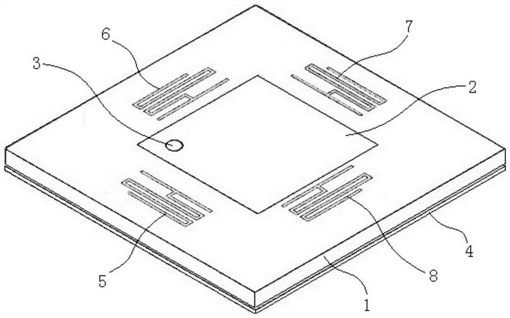
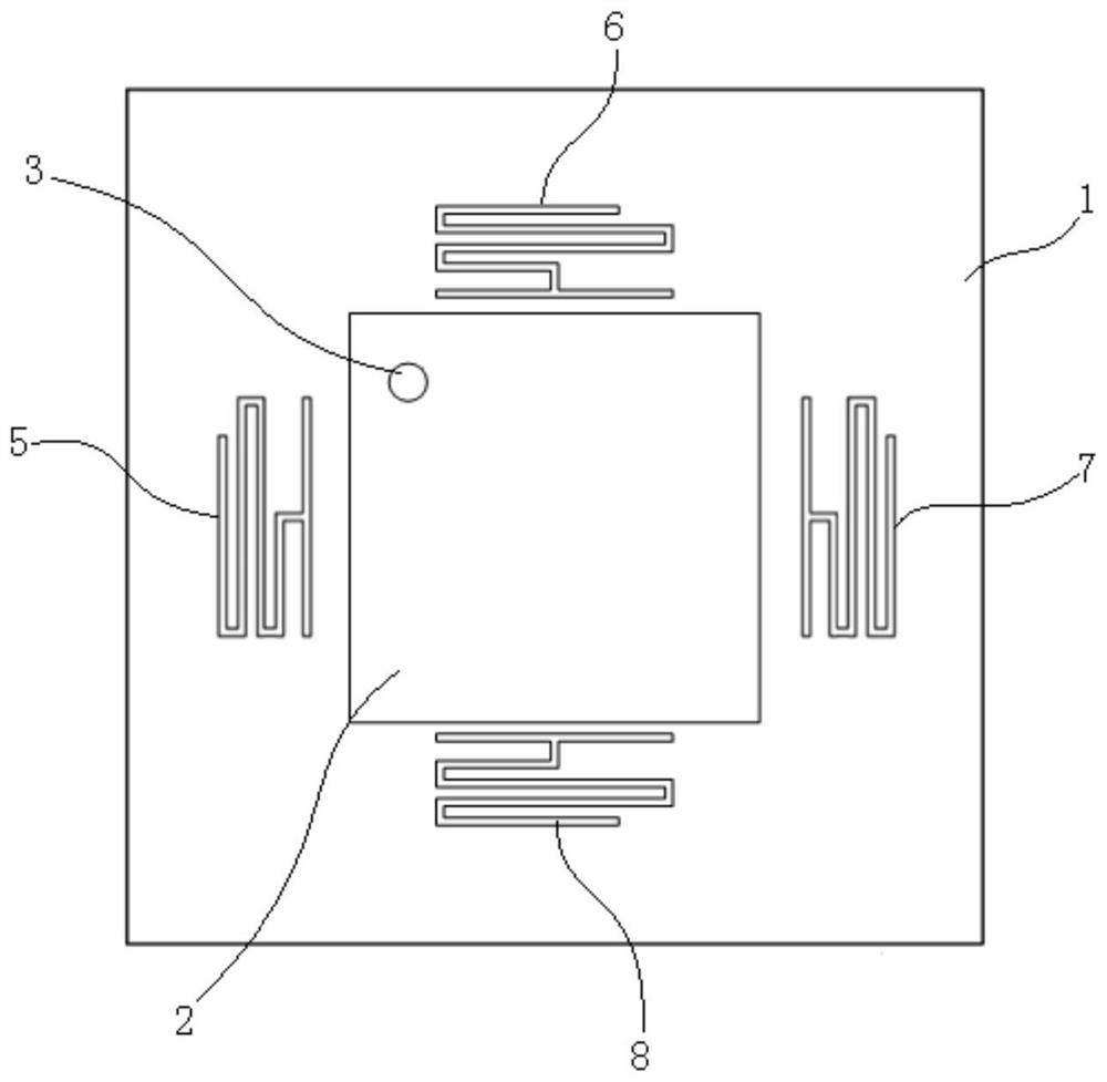
The invention relates to the technical field of microstrip antennas, and discloses a dual-frequency dual-circularly-polarized microstrip antenna, which comprises a dielectric substrate, a radiation patch, a feeding point, a metal floor, a first resonator and a second resonator, and is characterized in that the radiation patch and the metal floor are respectively positioned on the upper surface and the lower surface of the dielectric substrate, and the radiation patch is a rectangular patch; the feeding point is located on the diagonal line of the radiation patch, the first resonator and the second resonator are located outside the radiation patch and located on the two adjacent sides of the radiation patch respectively, the center of the first resonator and the center of the radiation patch are located on the same straight line, and the center of the second resonator and the center of the radiation patch are located on the same straight line. The resonant frequencies of the first resonator and the second resonator are not equal, the resonant frequencies of the first resonator, the second resonator and the radiation patch are similar, the antenna can work in two frequency bands and is dual-circularly polarized, the antenna has the advantages of a low profile, low cost, simple manufacturing and the like, the isolation degree of the two frequency bands is high, and an impedance characteristic is small.

Description

technical field [0001] The invention relates to the technical field of microstrip antennas, in particular to a dual-frequency dual circularly polarized microstrip antenna. Background technique [0002] With the rapid development of wireless communication systems, in order to meet better communication quality and higher communication capacity, circular polarization and dual-frequency or multi-frequency technology has become a research hotspot in the field of antennas in recent years, and circular polarization and multi-frequency The combination of technology has also become a research and design trend. An advantage of the microstrip antenna is that it is easy to obtain circular polarization, and it is easy to realize dual frequency bands and dual polarization. Although the most commonly used wireless communication polarization method is still linear polarization, the advantages of circularly polarized waves such as anti-interference, anti-rain and fog, and anti-attenuation m...

Claims


Application Information

Patent Timeline
Patent Type & Authority Applications(China)
IPC IPC(8): H01Q13/08H01P7/00H01Q1/38H01Q1/48H01Q5/20
CPCH01Q13/08H01Q1/38H01Q1/48H01Q5/20H01P7/00
Inventor 苏志孟吴琼森
Owner GUANGDONG UNIV OF TECH
Learn More