Gate circuit and digital circuit including same

A gate circuit and power supply technology, applied in logic circuits, exclusive-or circuits, logic circuits with logic functions, etc., to reduce circuit costs, avoid short-circuit power consumption, and maintain logic operation functions

Active Publication Date: 2021-07-09
HANGZHOU SILAN MICROELECTRONICS
View PDF3 Cites 1 Cited by
  • Summary
  • Abstract
  • Description
  • Claims
  • Application Information

AI Technical Summary

Problems solved by technology

Since the waveform of the input signal is not an ideal step signal, both the PMOS transistor and the NMOS transistor may be in the on state during the rising and falling of the input signal, thus forming a DC path between the power supply end and the ground end, resulting in a switch Short circuit power dissipation during

Method used


Image

  • Gate circuit and digital circuit including same
  • Gate circuit and digital circuit including same
  • Gate circuit and digital circuit including same

Examples


Embodiment Construction

[0063] Hereinafter, the present invention will be described in more detail with reference to the accompanying drawings. In the various figures, identical elements are indicated with similar reference numerals. For the sake of clarity, various parts in the drawings have not been drawn to scale. Also, some well-known parts may not be shown.

[0064] In the following, many specific details of the present invention are described, such as device structures, materials, dimensions, processing techniques and techniques, for a clearer understanding of the present invention. However, the invention may be practiced without these specific details, as will be understood by those skilled in the art.

[0065] The invention can be embodied in various forms, some examples of which are described below.

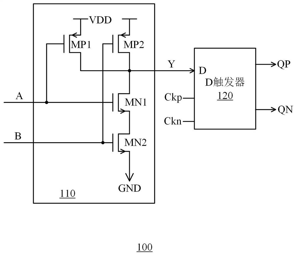
[0066] figure 1 A schematic circuit diagram of a digital circuit according to the prior art is shown. The digital circuit 100 includes an independently designed gate circuit 110 and a D fl...


PUM


Abstract

The invention discloses a gate circuit and a digital circuit comprising the same. The gate circuit comprises a first group of transistors, a second group of transistors and a third transistor which are positioned between a power supply end and a grounding end, wherein the grid electrode of the third transistor receives a clock signal, and the grid electrodes of the transistors in the first group of transistors and the second group of transistors are connected to the input end of the gate circuit so as to receive respective input signals; under the condition that the third transistor is conducted, the first group of transistors are connected to a power supply end, the second group of transistors are connected to a grounding end, and the first group of transistors and the second group of transistors are connected with each other; an intermediate node of the two is connected to the output end of the gate circuit so as to provide a trigger signal corresponding to a logic operation result; and in the transition stage of the input signal, the third transistor is switched off to cut off a direct-current path between the power supply end and the grounding end. Furthermore, according to the digital circuit, a gate circuit and a trigger are used as a combined circuit module for optimization design, so that the circuit cost is reduced.

Description

technical field [0001] The present invention relates to integrated circuit technology, and more particularly, to gate circuits and digital circuits containing gate circuits. Background technique [0002] In the digital part of the integrated circuit, gate circuits are used to implement basic logic operations or complex logic operations, and flip-flops are used to store the logic operation results of the gate circuits as data corresponding to one of two logic states, ie, 0 or 1. According to different logic operations, gate circuits can be divided into AND gates, OR gates, NOT gates, NAND gates, NOR gates, AND-NOR gates, XOR gates, etc. The logic operation result of the gate circuit is, for example, a pulse signal, and the flip-flop generates a steady-state level signal corresponding to a logic state based on the pulse signal. [0003] The gate circuit includes, for example, a PMOS transistor and an NMOS transistor connected in series between a power supply terminal and a gr...

Claims


Application Information

Patent Timeline
Patent Type & Authority Applications(China)
IPC IPC(8): H03K19/20H03K19/21H03K19/0944
CPCH03K19/20H03K19/215H03K19/0944H03K19/0013
Inventor 宋卫权陈向东
Owner HANGZHOU SILAN MICROELECTRONICS
Why Eureka
Try Eureka