
A fish pond bottom dredging device for marine fish farming

A dredging device and fishery technology, applied in the fields of application, fish farming, animal husbandry, etc., can solve the problems of fishermen who are easy to slip, dangerous, and unable to pump out stubborn sludge

Active Publication Date: 2021-11-19
GUANGDONG OCEAN UNIVERSITY
View PDF9 Cites 0 Cited by
  • Summary
  • Abstract
  • Description
  • Claims
  • Application Information

AI Technical Summary

Problems solved by technology

[0002] my country is the largest aquaculture country in the world, and the output of aquaculture aquatic products accounts for 70% of the world's total. The density of fry cultured in marine fish ponds is generally high, resulting in a large amount of feces, residual bait and other particulate matter deposited at the bottom of the pond, resulting in The deterioration of the pond water body will reduce the survival rate and growth rate of fish fry. The traditional method of dredging the bottom of fish ponds in marine fisheries is that fishermen carry sand pumps into the fish ponds to pump the sludge from the fish ponds to the shore. The water level in the fish pond is relatively deep and the visibility is low. Fishermen are prone to slipping and falling in the fish pond, causing danger. Moreover, when the existing fish pond bottom dredging device for marine fish farming cleans the fish pond, the sludge The water in the tank is pumped to the bank along with the sludge, resulting in a waste of water resources. At the same time, the existing fish pond bottom dredging device for marine fishery cultivation cannot remove the stubborn sludge at the bottom of the fish pond, and the dredging effect poor

Method used


Image

  • A fish pond bottom dredging device for marine fish farming
  • A fish pond bottom dredging device for marine fish farming
  • A fish pond bottom dredging device for marine fish farming

Examples


Embodiment Construction

[0022] The following will clearly and completely describe the technical solutions in the embodiments of the present invention with reference to the accompanying drawings in the embodiments of the present invention. Obviously, the described embodiments are only some, not all, embodiments of the present invention. Based on the embodiments of the present invention, all other embodiments obtained by persons of ordinary skill in the art without making creative efforts belong to the protection scope of the present invention.

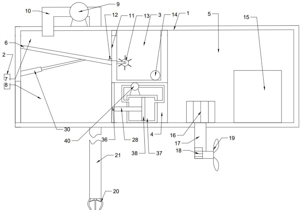
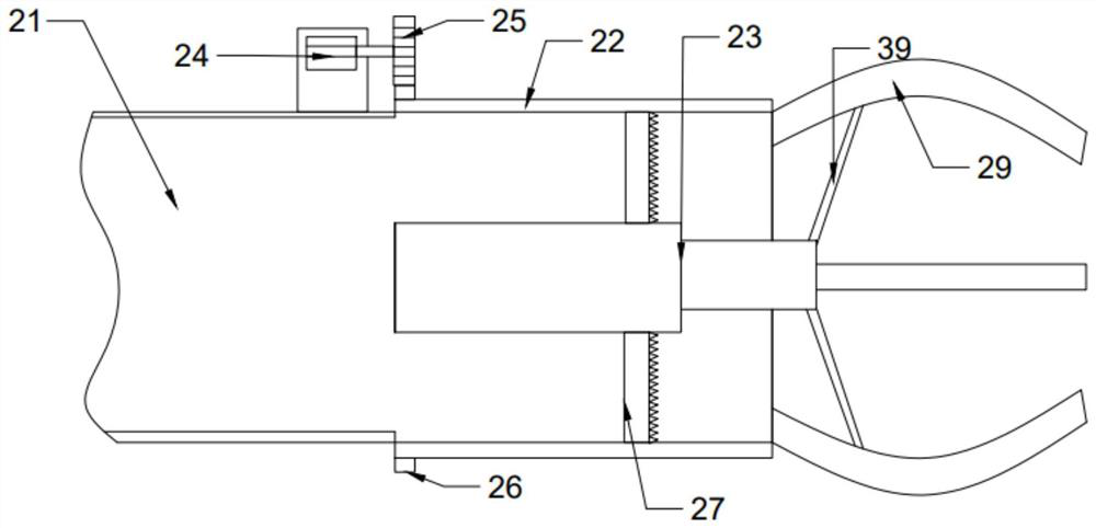
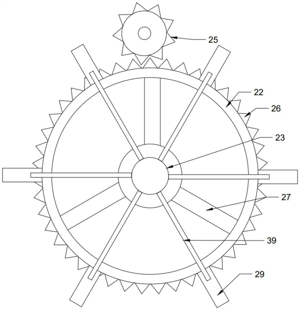
[0023] combined with Figure 1-Figure 5 Shown, a kind of dredging device at the bottom of a fishpond for marine fishery cultivation comprises a hull 1, and the hull 1 includes a sludge chamber 2, a drainage chamber 3, a cylinder chamber 4 and a power chamber 5, and the drainage chamber 3 and the cylinder chamber 4 are located in the sewage chamber. Between the mud chamber 2 and the power chamber 5, the cylinder chamber 4 is located below the drainage chamber 3...


PUM


Abstract

The invention discloses a fish pond bottom dredging device for marine fishery cultivation, which includes a hull, the hull includes a sludge chamber, a drainage chamber, a cylinder chamber and a power chamber, the sludge chamber is connected with a baffle plate, the The baffle divides the sludge chamber into two parts: a mud discharge area and a drying area. A pump is connected above the mud discharge area. One end of the pump is connected with a mud suction device, and the other end is connected with a mud discharge pipe. The other end of the mud discharge pipe extends into the mud discharge area, the mud discharge area is connected with a filter screen on the side wall of the lower side of the baffle, and the two sides of the filter screen are respectively connected with a mud scraper and a driving device. The power chamber is connected with a power storage device and a motor 1, the power output end of the motor 1 is connected with a hollow connecting rod 1, and the other end of the connecting rod 1 is sealed and connected with a motor 2, and the motor 2 The power output end runs through the connecting rod and is connected with paddles. The invention has the advantages that the sludge can be drained, and the sludge and water are separated and discharged from the ship hull respectively.

Description

technical field [0001] The invention relates to the technical field of marine fishery cultivation equipment, in particular to a fish pond bottom dredging device for marine fishery cultivation. Background technique [0002] my country is the largest aquaculture country in the world, and the output of aquaculture aquatic products accounts for 70% of the world's total. The density of fry cultured in marine fish ponds is generally high, resulting in a large amount of feces, residual bait and other particulate matter deposited at the bottom of the pond, resulting in The deterioration of the pond water body will reduce the survival rate and growth rate of fish fry. The traditional method of dredging the bottom of fish ponds in marine fisheries is that fishermen carry sand pumps into the fish ponds to pump the sludge from the fish ponds to the shore. The water level in the fish pond is relatively deep and the visibility is low. Fishermen are prone to slipping and falling in the fish ...

Claims


Application Information

Patent Timeline
Patent Type & Authority Patents(China)
IPC IPC(8): A01K63/10B63B35/00
CPCA01K63/10B63B35/00
Inventor 嵇海旭梁秀娟
Owner GUANGDONG OCEAN UNIVERSITY
Learn More