Drilling system for numerically-controlled machine tool spindle box and heat dissipating method of drilling system

A technology of CNC machine tools and spindle boxes, which is applied in the direction of boring/drilling, drilling/drilling equipment, boring machine/drilling machine parts, etc. It can solve the problem of impurities in the drill bit, improve the cooling effect, ensure the use efficiency, The effect of improving resource utilization

Active Publication Date: 2020-11-10
浙江侨宏机械制造有限公司
View PDF9 Cites 2 Cited by
  • Summary
  • Abstract
  • Description
  • Claims
  • Application Information

AI Technical Summary

Problems solved by technology

[0005] Aiming at the deficiencies in the prior art, the purpose of the present invention is to provide a drilling system for the spindle box of a numerically controlled machine tool and a heat dissipation method thereof, aiming at solving the problem that the existing drill bit contains a large amount of impurities and is exposed to high temperature for a long time in the above-mentioned background technology. state work problem

Method used


Image

  • Drilling system for numerically-controlled machine tool spindle box and heat dissipating method of drilling system
  • Drilling system for numerically-controlled machine tool spindle box and heat dissipating method of drilling system
  • Drilling system for numerically-controlled machine tool spindle box and heat dissipating method of drilling system

Examples


Embodiment 1

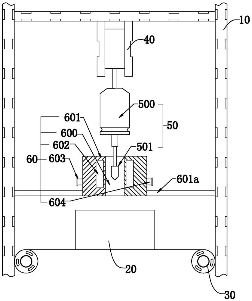
[0043] Such as figure 1 As shown, the present invention discloses a drilling system for a spindle box of a CNC machine tool, including a frame 10 and a moving mechanism 30 mounted on the frame 10 and used to control the movement of the spindle box 20. In a specific embodiment of the present invention Among them, it includes a drilling device 50 installed on the frame 10 and controlled by the lifting module 40 to open the headstock 20 and an output end installed on the frame 10 and having the drilling device 50 The heat dissipation device 60 of the movable heat dissipation cavity 600; wherein, the heat dissipation device 600 includes a heat dissipation body 601 having the heat dissipation cavity 600, at least one cooling cavity 602 disposed in the heat dissipation body 601, and a cooling cavity 602 disposed in the heat dissipation body The liquid inlet circulation port 603 and the liquid outlet circulation port 604 outside the cooling chamber 601 and communicated with the cooli...

Embodiment 2

[0051] Embodiment 2, the difference with embodiment 1 is that

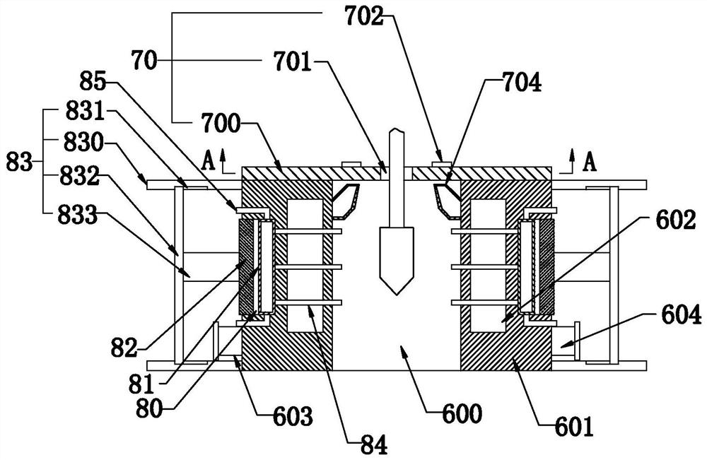
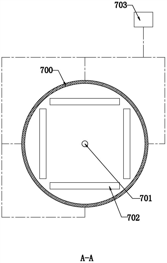
[0052] Such as Figure 2-Figure 4 As shown, in the specific embodiment of the present invention, it also includes a heat dissipation module 70 installed in the heat dissipation cavity 600 and communicated with the cooling cavity 602; wherein, the heat dissipation module 70 includes a heat dissipation module installed on the top of the heat dissipation body and has The base plate 700 of the opening 701 for the movable output end of the drilling device 50, several groups of heat dissipation ports 702 arranged on the base plate 700 and arranged at equidistant intervals around the opening 701, have several input ends and at least one output end, and each input end communicates with each group of heat dissipation ports 702, and several hollow air extraction devices 703, one end of which is respectively installed on the wall of the heat dissipation cavity 600, and fins 704 are arranged at equal intervals in the circumfe...

Embodiment 3

[0072] Embodiment 3, the difference with embodiment 2 is that

[0073] Such as Figure 5-Figure 7 As shown, in a specific embodiment of the present invention, at least four synchronous wheels 90 arranged at equidistant intervals in the circumferential direction of the opening 701 and driven by a plc motor are rotatably connected to the base plate 700, and are transmission-connected to each synchronous wheel. The transmission belt 91 on the transmission belt 90, several dust raising modules 92 which are installed on the transmission belt 91 and are respectively located between the synchronous wheels 90 and are controlled to reciprocate between the adjacent synchronous wheels 90 by the transmission belt 91; The module 92 includes a dust blowing cylinder 920 installed on the transmission belt 91 and supplied with air by an air pump, and several dust blowing cylinders 920 arranged on the dust blowing cylinder 920 and used to supply air to the output end of the drilling device 50 a...


PUM


Abstract

The invention relates to a drilling system for a numerically-controlled machine tool spindle box and a heat dissipating method of the drilling system. The drilling system comprises a rack and a movingmechanism used for controlling the spindle box to move, and is characterized by further comprising a drilling device and a heat dissipating device, wherein the drilling device is mounted on the rack,controlled by a lifting module to rise and fall, and used for drilling holes in the spindle box; the heat dissipating device is mounted on the rack, and comprises a heat dissipating cavity, a heat dissipating body, at least one cooling cavity, a liquid injecting circulation port and a liquid discharging circulation port; the heat dissipating cavity is used for the movement of the output end of the drilling device; the heat dissipating body is provided with the heat dissipating cavity; the cooling cavity is arranged in the heat dissipating body; and the liquid injecting circulation port and the liquid discharging circulation port are arranged outside the heat dissipating body and communicate with the cooling cavity. The drilling system and the heat dissipating method have the beneficial effects that the use is stable and the precision is high.

Description

technical field [0001] The invention relates to the technical field of spindle box drilling, in particular to a drilling system for a spindle box of a numerically controlled machine tool and a heat dissipation method thereof. Background technique [0002] The spindle box is the most important component of the machine tool. It is mainly used to arrange the transmission parts and additional devices of the machine tool. Therefore, when the spindle box is processed, it is usually necessary to open holes to ensure its use; [0003] However, after the current drilling device (or system) for the main shaft drills the main shaft box, the drill bit will generate a lot of heat due to continuous work, so that the drill bit is in a high-temperature working state for a long time, which easily affects the service life of the drill bit. ; [0004] Not only that, but after the existing headstock is drilled, a large amount of iron filings will be adsorbed on the drill bit, so that the drill...

Claims


Application Information

Patent Timeline
IPC IPC(8): B23B41/00B23B47/00B23Q11/10
CPCB23B41/00B23B47/00B23Q11/10
Inventor 戴建福戴思聪石琪琪
Owner 浙江侨宏机械制造有限公司
Why Eureka
Try Eureka