Drilling system and heat dissipation method for spindle box of CNC machine tool
A technology of CNC machine tools and spindle boxes, which is applied in the directions of boring/drilling, drilling/drilling equipment, and components of boring machines/drilling machines, etc., can solve the problem of impurities in the drill bit, improve the cooling effect, ensure the cooling effect, Ensure efficient use of the effect
- Summary
- Abstract
- Description
- Claims
- Application Information
AI Technical Summary
Problems solved by technology
Method used
Image
Examples
Embodiment 1
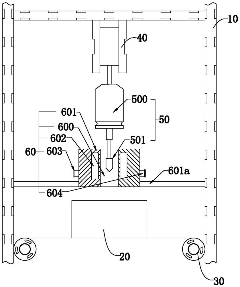
[0043] like figure 1 As shown, the present invention discloses a drilling system for a spindle box of a CNC machine tool, including a frame 10 and a moving mechanism 30 mounted on the frame 10 and used to control the movement of the spindle box 20. In a specific embodiment of the present invention Among them, it includes a drilling device 50 installed on the frame 10 and controlled by the lifting module 40 to open the headstock 20 and an output end installed on the frame 10 and having the drilling device 50 The heat dissipation device 60 of the active heat dissipation chamber 600; wherein, the heat dissipation device 60 includes a heat dissipation body 601 having the heat dissipation chamber 600, at least one cooling cavity 602 disposed in the heat dissipation body 601, and a cooling chamber 602 disposed in the heat dissipation body The liquid inlet circulation port 603 and the liquid outlet circulation port 604 outside the cooling chamber 601 and communicated with the cooling...
Embodiment 2
[0051] Embodiment 2, the difference with embodiment 1 is that
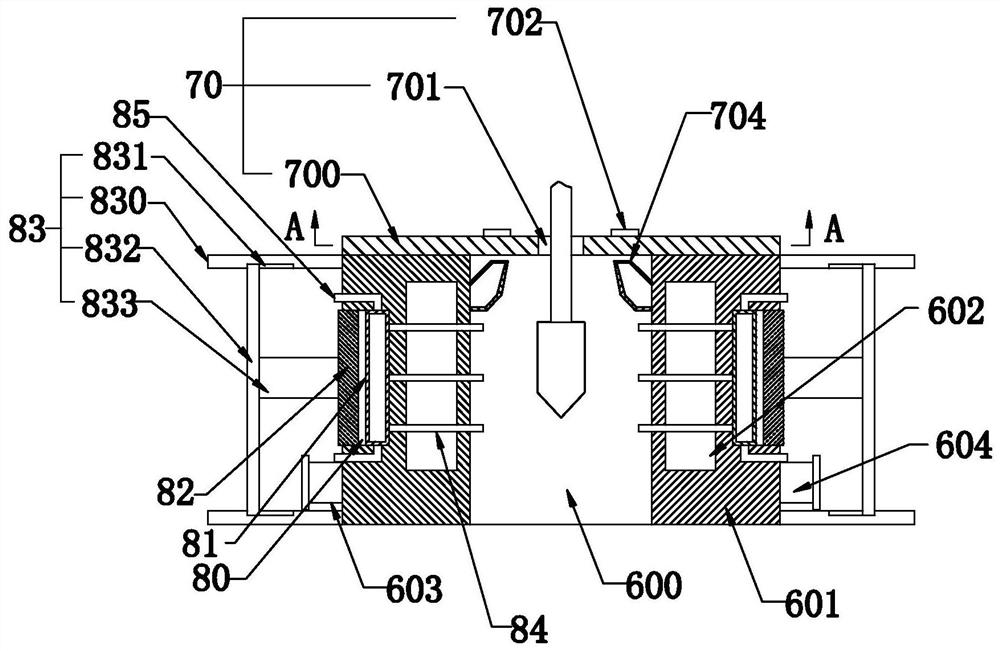
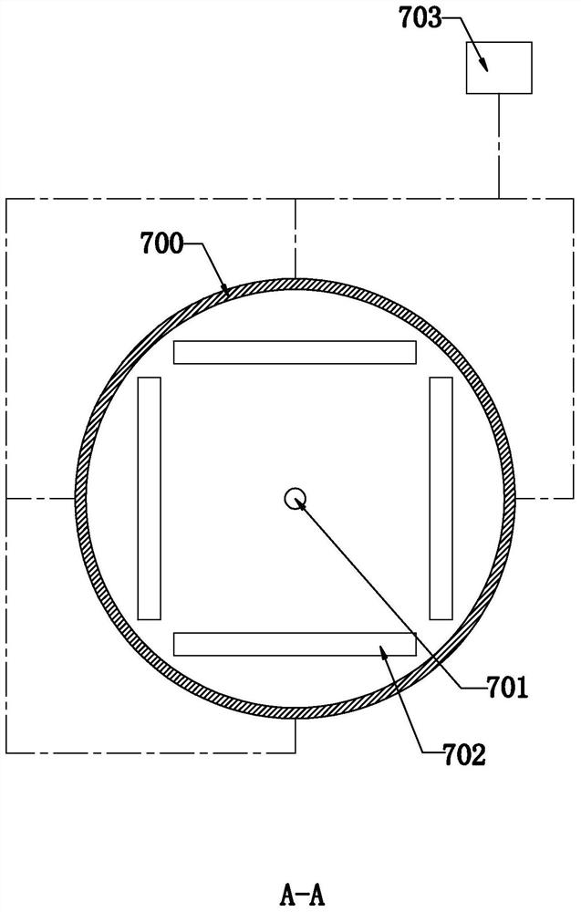
[0052] like Figure 2-Figure 4 As shown, in the specific embodiment of the present invention, it also includes a heat dissipation module 70 installed in the heat dissipation cavity 600 and communicated with the cooling cavity 602; wherein, the heat dissipation module 70 includes a heat dissipation module installed on the top of the heat dissipation body and has The base plate 700 of the opening 701 for the movable output end of the drilling device 50, several groups of heat dissipation ports 702 arranged on the base plate 700 and arranged at equidistant intervals around the opening 701, have several input ends An air extraction device 703 connected to at least one output end and each input end communicates with each group of cooling ports 702, and a plurality of hollow fins 704 with one end respectively installed on the wall of the heat dissipation chamber 600 and arranged at equal intervals in the circumferential...
Embodiment 3
[0072] Embodiment 3, the difference with embodiment 2 is that
[0073] like Figure 5-Figure 7 As shown, in a specific embodiment of the present invention, at least four synchronous wheels 90 arranged at equidistant intervals in the circumferential direction of the opening 701 and driven by a plc motor are rotatably connected to the base plate 700, and are transmission-connected to each synchronous wheel. The transmission belt 91 on the transmission belt 90, several dust raising modules 92 which are installed on the transmission belt 91 and are respectively located between the synchronous wheels 90 and are controlled to reciprocate between the adjacent synchronous wheels 90 by the transmission belt 91; The module 92 includes a dust blowing cylinder 920 installed on the transmission belt 91 and supplied with air by an air pump, and several dust blowing cylinders 920 arranged on the dust blowing cylinder 920 and used to supply air to the output end of the drilling device 50 and / ...
PUM
 Abstract
Description
Claims
Application Information
 - R&D
- Intellectual Property
- Life Sciences
- Materials
- Tech Scout
- Unparalleled Data Quality
- Higher Quality Content
- 60% Fewer Hallucinations
Browse by: Latest US Patents, China's latest patents, Technical Efficacy Thesaurus, Application Domain, Technology Topic, Popular Technical Reports.
© 2025 PatSnap. All rights reserved.Legal|Privacy policy|Modern Slavery Act Transparency Statement|Sitemap|About US| Contact US: help@patsnap.com


