
Novel directional microwave ablation antenna based on substrate integrated coaxial cable

A technology of coaxial cable and substrate integration, which is applied in microwave surgical instruments, surgical instrument parts, medical science, etc., can solve the problems of difficult access to the central area of ​​the tumor, difficult impedance matching, high antenna cost, etc., to achieve strong Practical value, good for integration and low cost

Active Publication Date: 2021-07-13
UNIV OF ELECTRONIC SCI & TECH OF CHINA
View PDF19 Cites 0 Cited by
  • Summary
  • Abstract
  • Description
  • Claims
  • Application Information

AI Technical Summary

Problems solved by technology

[0002]In recent years, the application of microwaves in the medical industry has gradually increased, and microwave ablation technology is also considered to be an important means of treating tumors. Higher requirements are also put forward for the structure of the ablation antenna. The traditional microwave ablation antenna basically presents an axisymmetric structure, so the area used for microwave ablation is also axisymmetric. However, in some ablation scenarios, axisymmetric ablation The area may not be suitable and ideal, for example, vital organs that should not be ablated may be near the target ablation zone, and the central region of the tumor may not be easily accessible, so in this case, a method that can be placed on the periphery of the tumor to generate Microwave ablation antenna directed at the ablation zone, thus enabling better ablation procedures
At present, most microwave ablation antennas are designed based on the traditional coaxial structure. This structure has large power capacity, small cross-sectional area, and little harm to the patient. However, the traditional coaxial line is round and coaxial, and the antenna is processed on this structure. High cost, low precision, difficult to perform impedance matching, and the freedom of antenna structure design brought about by processing conditions has certain limitations

Method used


Image

  • Novel directional microwave ablation antenna based on substrate integrated coaxial cable
  • Novel directional microwave ablation antenna based on substrate integrated coaxial cable
  • Novel directional microwave ablation antenna based on substrate integrated coaxial cable

Examples


Embodiment Construction

[0024] In order to make the object, technical solution and advantages of the present invention clearer, the present invention will be further described in detail below in conjunction with the accompanying drawings and embodiments. It should be understood that the specific embodiments described here are only used to explain the present invention, not to limit the present invention.

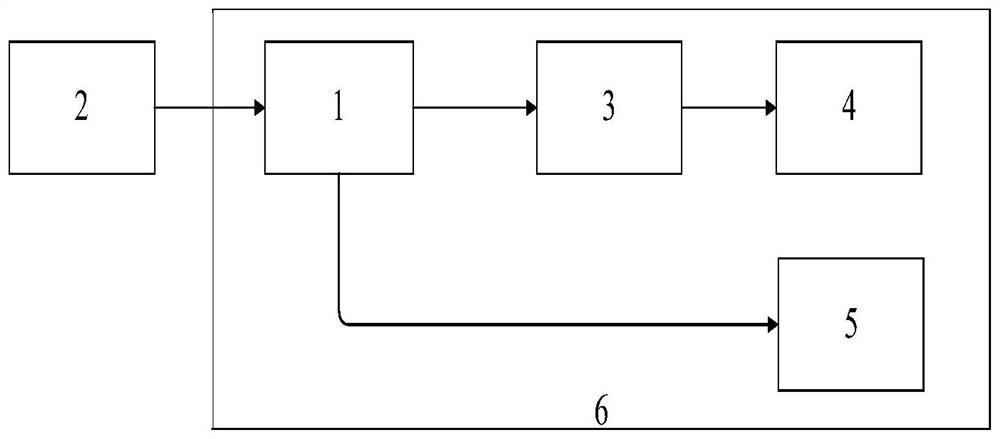
[0025] In the embodiment of the present invention, such as figure 1 Shown is a functional block diagram of a novel directional microwave ablation antenna based on a substrate-integrated coaxial cable of the present invention, including a substrate-integrated coaxial cable structure 1, a feeding structure 2, a matching structure 3, a radiation structure 4, and a reflection structure 5. Protective sheath structure 6; wherein the feed structure 2 is connected to the substrate-integrated coaxial cable structure 1, the matching structure 3 and the radiation structure 4 are both in the substrate-integrat...


PUM

PropertyMeasurementUnit
Lengthaaaaaaaaaa
Widthaaaaaaaaaa
Lengthaaaaaaaaaa

Abstract

The invention discloses a novel directional microwave ablation antenna based on a substrate integrated coaxial cable. The antenna comprises a substrate integrated coaxial cable structure, a feed structure, a matching structure, a radiation structure, a reflection structure and a protective sleeve structure; wherein the feed structure is connected with the substrate integrated coaxial cable structure, the matching structure and the radiation structure are both located in the substrate integrated coaxial cable structure, the reflection structure is connected with the substrate integrated coaxial cable structure, and the substrate integrated coaxial cable structure, the feed structure, the matching structure, the radiation structure and the reflection structure are located in the protection sleeve structure. The substrate integrated coaxial cable junction adopted by the invention is low in use cost, high in precision and simple and quick to manufacture, a matching structure adopts a coplanar waveguide form, the working stability of the antenna is improved, integration is facilitated; meanwhile, the problem that a traditional ablation antenna cannot complete directional area heating is solved by adopting a directional heating mode, so that a foundation is laid for wide application of microwave ablation antennas in the future.

Description

technical field [0001] The invention relates to the technical field of microwave ablation, in particular to a novel directional microwave ablation antenna based on a substrate-integrated coaxial cable. Background technique [0002] In recent years, the application of microwaves in the medical industry has gradually increased, and microwave ablation technology is also considered to be an important means of treating tumors. At present, due to the different ablation areas, higher requirements are placed on the structure of the ablation antenna. The microwave ablation antenna basically presents an axisymmetric structure, so the region used for microwave ablation is also axisymmetric. However, in some ablation scenarios, the axisymmetric ablation region may not be suitable and ideal, for example, the area that should not be ablated Vital organs may be near the target ablation zone, and the central area of ​​the tumor may not be easily accessible, so in this case, a microwave abla...

Claims


Application Information

Patent Timeline
IPC IPC(8): A61B18/18
CPCA61B18/1815A61B2018/1853
Inventor 林先其郭靖文章李晨楠
Owner UNIV OF ELECTRONIC SCI & TECH OF CHINA
Learn More