Boring machine with spindle nose provided with cooling system
A headband and spindle technology, applied in boring/drilling, maintenance and safety accessories, drilling/drilling equipment, etc., can solve the problem of rising surface temperature of the boring head, debris sticking to additional workpieces, and reducing processing efficiency and other problems, to achieve the effect of reducing secondary processing, increasing contact area, and improving processing efficiency
- Summary
- Abstract
- Description
- Claims
- Application Information
AI Technical Summary
Problems solved by technology
Method used
Image
Examples
Embodiment 1
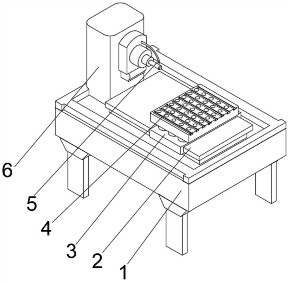
[0034] see Figure 1-2 , the present invention provides a technical solution: a boring machine with a cooling system for the spindle head, including a main body, a processing device 6 is provided at the middle position on the left side of the top of the main body 1, and a water spray pipe is connected to the top of the outer wall of one side of the processing device 6 5. The workbench 2 is fixedly connected to the top right side of the main body 1, and the top right side of the workbench 2 is provided with a mobile frame 3. A processing platform 4 is fixedly connected to the top.
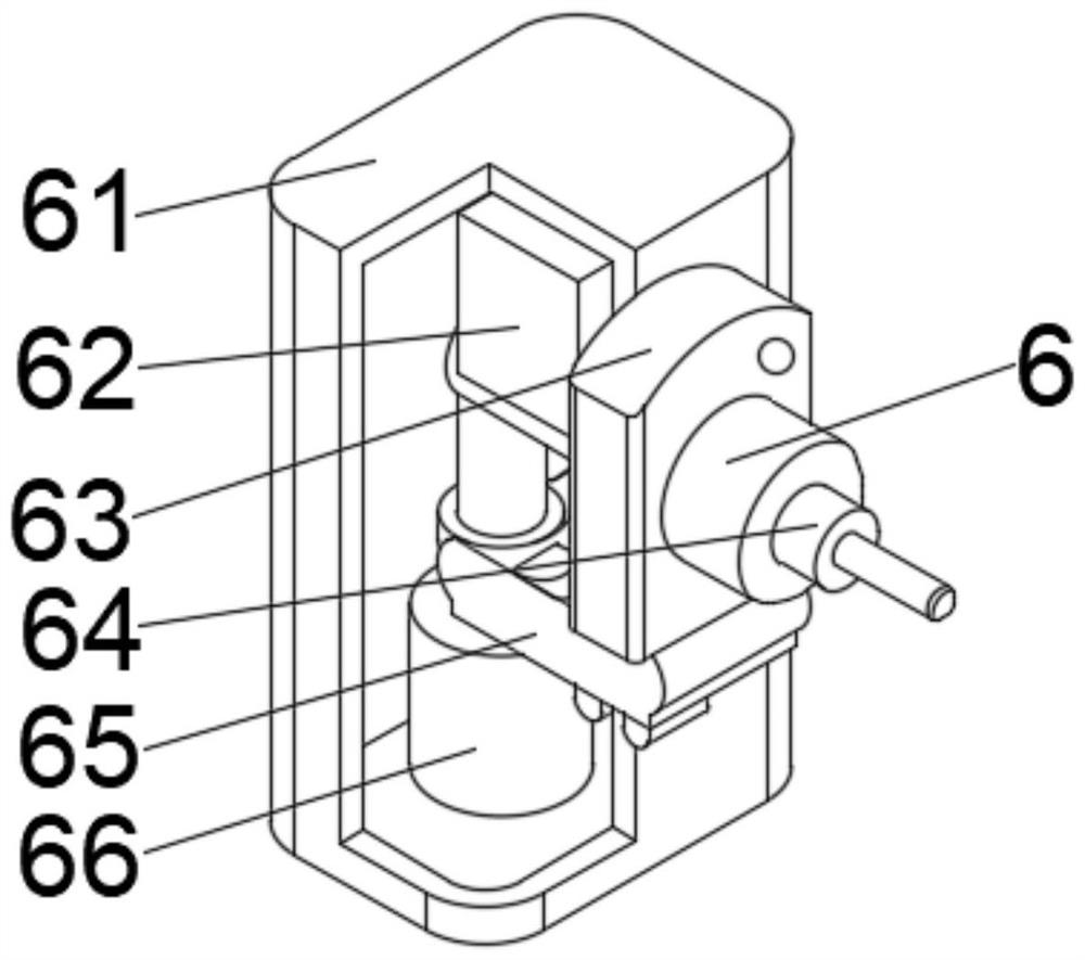
[0035] Wherein, processing device 6 comprises column 61, and the middle part of one side outer wall of column 61 is provided with fixing mechanism 63, and the middle part of right side outer wall of fixing mechanism 63 is fixedly connected with boring head body 64, and the right side outer wall of column 61 is positioned at the bottom of fixing mechanism 63 An auxiliary mechanism 65 is provided. The ...
Embodiment 2
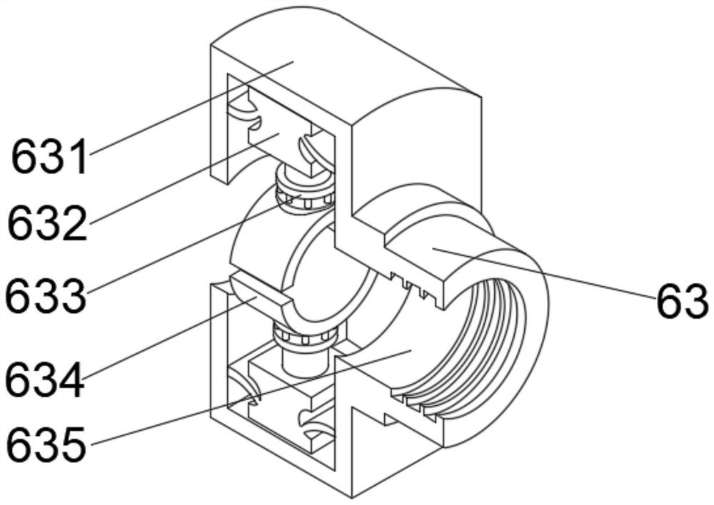
[0038] see Figure 1-4 , on the basis of Embodiment 1, the present invention provides a technical solution: component 1 of the fixing mechanism 63 includes a protective cover 631, the middle part of the outer wall on the right side of the protective cover 631 is fixedly connected with a fixer 635, and the inner walls on both sides of the protective cover 631 A fixed bracket 632 is fixedly connected, and a fixed telescopic column 633 is fixedly connected to a position away from the protective cover 631 of the fixed bracket 632 , and an arc ring 634 is fixedly connected to an end of the fixed telescopic column 633 away from the fixed bracket 632 .
[0039] Wherein, the first component of the auxiliary mechanism 65 includes an auxiliary block 651, the top right side of the auxiliary block 651 is fixedly connected with a support plate 653, the middle position of the inner cavity top of the auxiliary block 651 is fixedly connected with a ventilating partition 652, and the inner cavi...
Embodiment 3
[0042] see Figure 1-6 , on the basis of Embodiment 1 and Embodiment 2, the present invention provides a technical solution: component 2 of the fixing mechanism 63 includes a fitting plate d1, and the left outer wall of the fitting plate d1 is fixedly connected with a clamp d4, and the clamp d4 The inner walls on both sides of d4 are fixedly connected with rubber blocks d5, and the middle part of the fitting plate d1 away from the clamp d4 is fixedly connected with the compression block d2, and the position of the fitting plate d1 of the fitting plate d1 away from the clamp d4 is located in the compression block Both sides of d2 are fixedly connected with a block d3.
[0043] Among them, the second component of the auxiliary mechanism 65 includes the bottom plate t1, the top middle of the bottom plate t1 is fixedly connected with the force plate t2, the top right side of the force plate t2 is fixedly connected with the circulation device t4, and the front middle part of the ci...
PUM
 Abstract
Description
Claims
Application Information
 - R&D
- Intellectual Property
- Life Sciences
- Materials
- Tech Scout
- Unparalleled Data Quality
- Higher Quality Content
- 60% Fewer Hallucinations
Browse by: Latest US Patents, China's latest patents, Technical Efficacy Thesaurus, Application Domain, Technology Topic, Popular Technical Reports.
© 2025 PatSnap. All rights reserved.Legal|Privacy policy|Modern Slavery Act Transparency Statement|Sitemap|About US| Contact US: help@patsnap.com


