Mechanical automatic polishing device capable of adjusting clamping force

A mechanical and strength technology, which is applied in the field of mechanical automatic grinding devices, can solve the problems of the surrounding environment, difficulty in adjusting the clamping strength according to the demand, and the generation of dust, etc.

Active Publication Date: 2021-07-13
CHANGDE CITY ZHONGKAI MACHINERY IND
View PDF12 Cites 2 Cited by
  • Summary
  • Abstract
  • Description
  • Claims
  • Application Information

AI Technical Summary

Problems solved by technology

[0006] The purpose of the present invention is to provide a mechanical automatic grinding device that can adjust the clamping force, so as to solve the problems in the adjustment of the clamping force proposed in the above-mentioned background technology. In the process, it is difficult to adjust the appropriate clamping force according to the demand. At the same time, there are still some deficiencies in the suction of the dust generated during the grinding process. During the grinding process of the workpiece, a certain amount of dust will be generated. If the dust cannot be removed in time deal with problems that have a certain impact on the surrounding environment

Method used


Image

  • Mechanical automatic polishing device capable of adjusting clamping force
  • Mechanical automatic polishing device capable of adjusting clamping force
  • Mechanical automatic polishing device capable of adjusting clamping force

Examples


Embodiment Construction

[0029] The following will clearly and completely describe the technical solutions in the embodiments of the present invention with reference to the accompanying drawings in the embodiments of the present invention. Obviously, the described embodiments are only some, not all, embodiments of the present invention. Based on the embodiments of the present invention, all other embodiments obtained by persons of ordinary skill in the art without making creative efforts belong to the protection scope of the present invention.

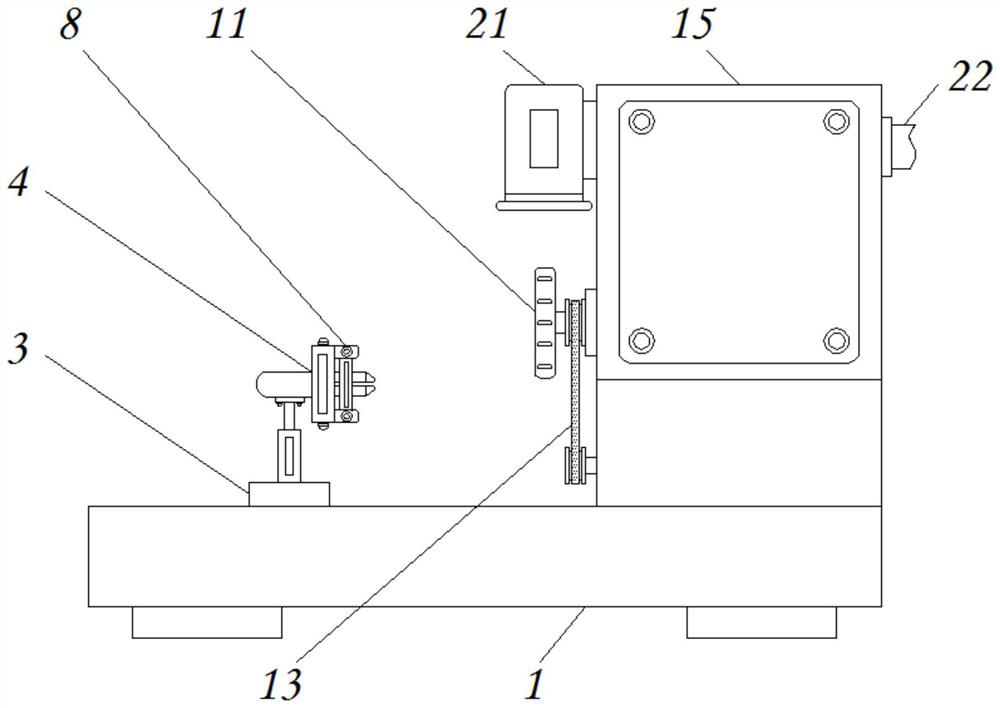
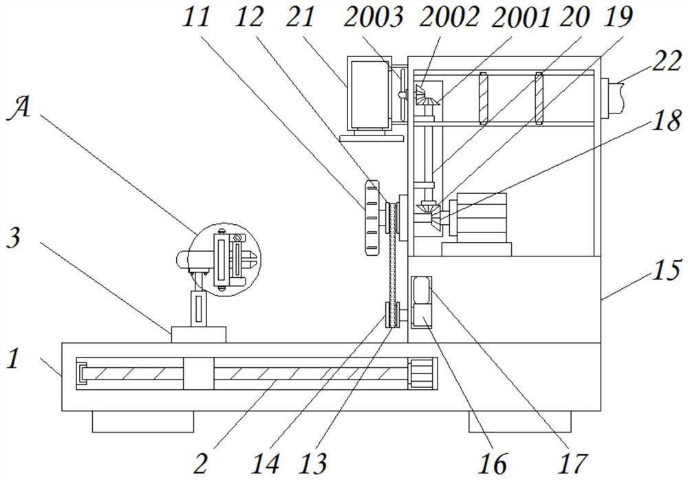
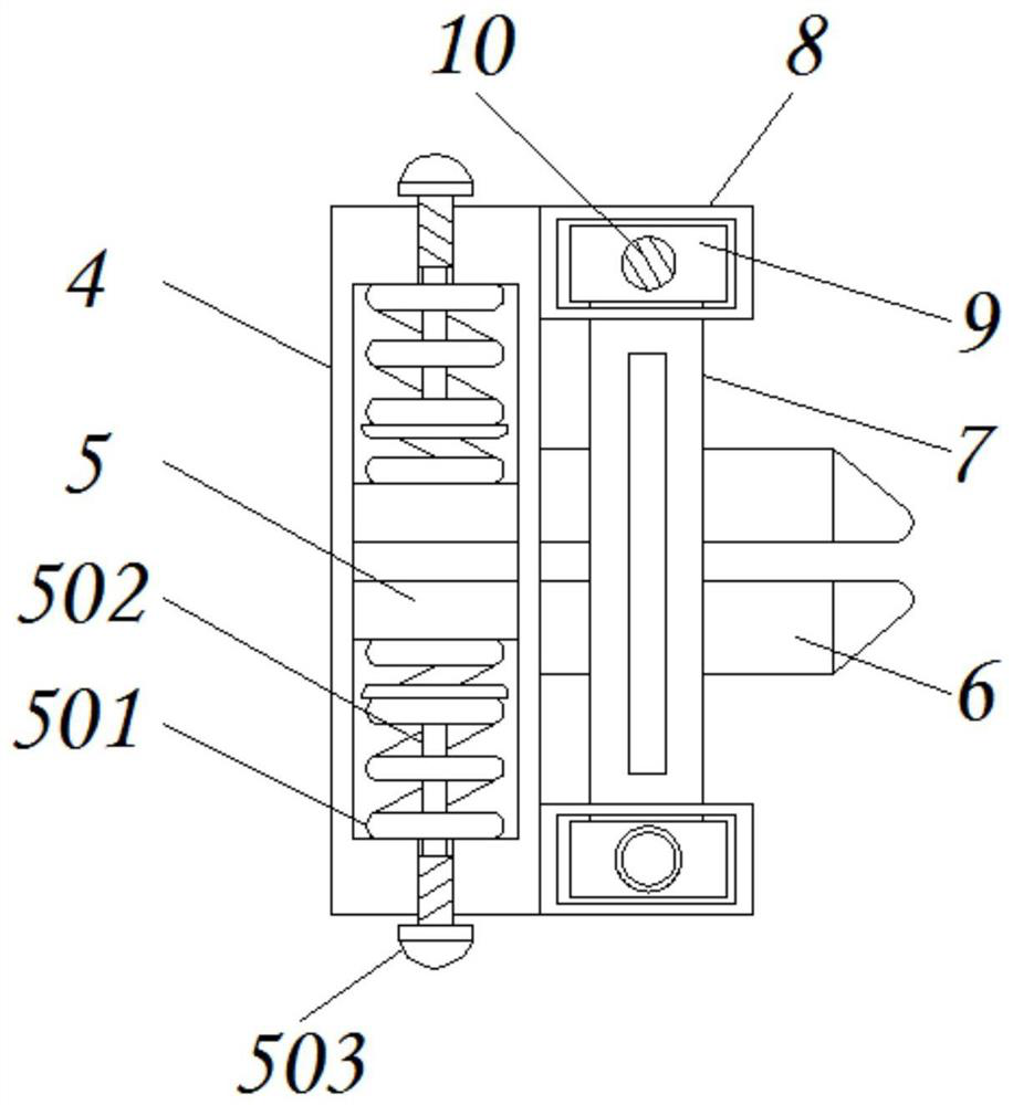
[0030] see Figure 1-8 , the present invention provides a technical solution: a mechanical automatic grinding device that can adjust the clamping force, including a fixed base 1, a transmission rod 2, a connecting seat 3, a hollow block 4, a movable block 5, a telescopic spring 501, a connecting rope 502, rotating knob 503, splint 6, limit plate 7, first connecting block 8, slider 9, rotating rod 10, frosted disc 11, rotating wheel 12, connecting belt 13, mova...


PUM


Abstract

The invention discloses a mechanical automatic polishing device capable of adjusting the clamping force. The mechanical automatic polishing device capable of adjusting the clamping force comprises a fixed base, a limiting plate, a grinding disc and a rotating gear. A transmission rod is movably installed in the fixed base, the top of the transmission rod is connected with a connecting base, and the top of the connecting base is fixedly connected with a hollow block. A movable block is installed in the hollow block, a clamping plate is fixedly connected to one side of the movable block, the limiting plate is fixed to the outer side of the clamping plate, first connecting blocks are fixedly installed at the two ends of the limiting plate, sliding blocks are installed in the first connecting blocks, rotating rods are connected to the middles of the sliding blocks, and the grinding disc is installed on the right side of the limiting plate. The mechanical automatic polishing device capable of adjusting the clamping force has the secondary polishing effect, raised dust generated by polishing can be sucked away, meanwhile, the appropriate clamping force can be adjusted according to requirements, and a user can conveniently adjust and use the mechanical automatic polishing device.

Description

technical field [0001] The invention relates to the technical field of mechanical processing, in particular to a mechanical automatic grinding device capable of adjusting clamping force. Background technique [0002] Grinding is a common processing method. The rough surface of the workpiece is processed by specific tools to make the surface of the workpiece smoother. Grinding can also remove burrs, floating rust, oil stains, etc. on the surface of the workpiece. Now people In order to speed up the progress of the workpiece, a mechanical grinding device will be used to grind the workpiece. The traditional grinding device still has certain deficiencies, such as: [0003] 1. The current traditional mechanical automatic grinding device still has certain deficiencies in the adjustment of the clamping force. During the grinding process of the workpiece, the clamping mechanism of the workpiece will be used to clamp and fix the workpiece. In the clamping and fixing of workpieces wi...

Claims


Application Information

Patent Timeline
Patent Type & Authority Applications(China)
IPC IPC(8): B24B19/00B24B9/00B24B27/033B24B21/00B24B21/18B24B27/00B24B41/00B24B41/06B24B47/00B24B47/12B24B55/06B24B55/08B24B55/12B01D46/12
CPCB24B19/00B24B9/00B24B27/033B24B41/06B24B47/00B24B41/007B24B21/00B24B21/18B24B27/0076B24B47/12B24B55/06B24B55/12B24B55/08B01D46/12Y02P70/10
Inventor 汪云兰
Owner CHANGDE CITY ZHONGKAI MACHINERY IND
Why Eureka
Try Eureka