
Centrifugal pump

A centrifugal pump and pump stand technology, applied in the field of centrifugal pumps, can solve the problems of damage, the centrifugal pump is susceptible to moisture, and it is difficult to ensure that the centrifugal pump is installed in parallel with the horizontal plane, and achieves the effect of improving installation quality, improving use effect and service life.

Active Publication Date: 2021-07-13
ZHUOZHOU IRONWORK PETROCHEM EQUIP MFG
View PDF10 Cites 1 Cited by
  • Summary
  • Abstract
  • Description
  • Claims
  • Application Information

AI Technical Summary

Problems solved by technology

[0004] (1) During the installation process of traditional centrifugal pumps, when the fixed plane and the horizontal plane are inclined or the surface is uneven, it is difficult to ensure that the centrifugal pump is installed parallel to the horizontal plane, thus affecting the subsequent use of the centrifugal pump
[0005] (2) During the use of traditional centrifugal pumps, when the installation environment is harsh, the centrifugal pumps are very susceptible to moisture or contact with liquids, which will lead to damage and even safety accidents

Method used


Image

  • Centrifugal pump
  • Centrifugal pump
  • Centrifugal pump

Examples


Embodiment Construction

[0032] In order to make the technical means, the creation of the present invention, the purpose and energy is easy to understand, the following combinations Figure 1 to 8 Further, the invention is further illustrated.

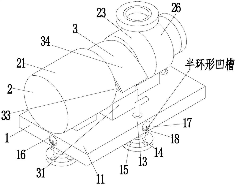
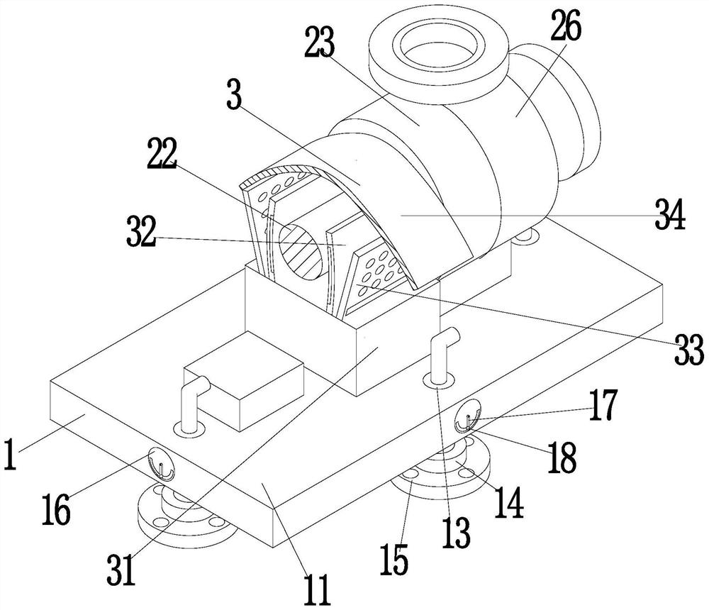
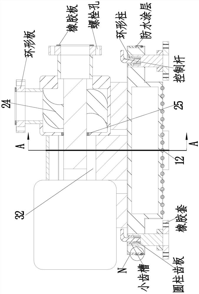
[0033] A centrifugal pump comprising a base 1, a pump frame 2, and a housing 3, the base 1 is fixedly mounted having a pump frame 2, and the upper end surface of the base 1 is fixed to the outside of the pump frame 2; there is:

[0034] The base 1 includes an embedded panel 11, a ball 12, a screw column 13, a nut 14, a positioning plate 15, a circular feet 16, a straight rod 17 and a lead ball 18, and the lower end surface of the inverted parallelene plate 11 is uniform in sliding cooperation The rollers 12 are connected, and the inverted panel 11 is uniformly connected in a threaded connection. The threaded column 13 is connected in the lower outer end surface of the threaded connection. The nut is connected to the nut 14, the nut sheet 14 lower end surface fixed ...


PUM


Abstract

The invention relates to a centrifugal pump which comprises a base, a pump frame and a shell. The pump frame is fixedly installed on the upper end face of the base, the shell is fixedly installed on the portion, located at the outer side of the pump frame, of the upper end face of the base, the base comprises an inverted-convex plate, a ball, a threaded column, a nut pair, a positioning plate, a round ruler, a straight rod and a lead ball, and the shell comprises a fixing plate, a damp-proof shell, a heat dissipation shell and a water retaining shell. The centrifugal pump is positioned and fixed through the base, meanwhile, the centrifugal pump is still installed parallel to the horizontal plane under the condition that the fixed plane is not flat, and therefore the installation quality of the centrifugal pump is improved; a liquid discharging pipe and a liquid inlet pipe are conveniently connected and fixed through the pump frame, and the condition that liquid in the external environment enters the centrifugal pump, and consequently the service life and the using effect of the centrifugal pump are influenced is avoided through the shell; and meanwhile, a main shaft of the centrifugal pump is kept dry, heat dissipation can be conducted, and therefore the using effect of the centrifugal pump is further improved, and the service life of the centrifugal pump is further prolonged.

Description

Technical field [0001] The present invention relates to the field of pumps, and is specifically a centrifugal pump. Background technique [0002] The centrifugal pump is designed according to the principle of centrifugation. The high-speed rotating impeller blade boosted water, and the water is taken out, so that the purpose of delivery, the centrifugal pump is widely specified, mainly for the horizontal centrifugal pump, the advantages of the horizontal centrifugal pump There is a simple structure, convenient maintenance, no vibration in fixed installation, good seal, low noise, convenient maintenance, low price, but due to the horizontal position of the horizontal centrifugal pump, the horizontal centrifugal pump is placed To take up more place, and because of the limitations of the suction, the water pump is installed very low, easy to be tidy, flooded, and affects safe operation. [0003] During the installation of the centrifugal pump, due to the structural limit of the cent...

Claims


Application Information

Patent Timeline
Patent Type & Authority Applications(China)
IPC IPC(8): F04D1/00F04D29/62F04D29/58F04D29/42F04D29/02B01D53/26
CPCF04D1/00F04D29/628F04D29/588F04D29/426F04D29/026B01D53/26
Inventor 李永帅
Owner ZHUOZHOU IRONWORK PETROCHEM EQUIP MFG
Learn More