Hybrid transmission electro-hydraulic limp control oil way and method

A technology for controlling oil circuit and control method, which is applied in the direction of transmission control, components with teeth, belt/chain/gear, etc., and can solve the problems of complexity, long response time, and the inability of the transmission to limp.

Active Publication Date: 2021-07-13
XIAN FASHITE AUTOMOBILE TRANSMISSION CO LTD
View PDF7 Cites 1 Cited by
  • Summary
  • Abstract
  • Description
  • Claims
  • Application Information

AI Technical Summary

Problems solved by technology

The existing hydraulic control system is relatively complex, and the response time is long, but the control of the main oil pressure adopts its own feedback control, and the control of the gear shift actuator adopts a one-to-one control method, which makes the hydraulic control simple and quick in response
[0003] The operating conditions of modern vehicles are often determined according to the actual situation, and sometimes some problems may occur in harsh environments. The probability of failures under working conditions will also continue to increase. When a failure occurs during the driving of the car, causing the transmission to fail to work normally, the transmission will take some measures to ensure that the car can complete the driving function under limited conditions, but for hybrid transmissions , there is currently no failure in the field to cause a limp function when the transmission does not work properly

Method used


Image

  • Hybrid transmission electro-hydraulic limp control oil way and method
  • Hybrid transmission electro-hydraulic limp control oil way and method
  • Hybrid transmission electro-hydraulic limp control oil way and method

Examples


Embodiment Construction

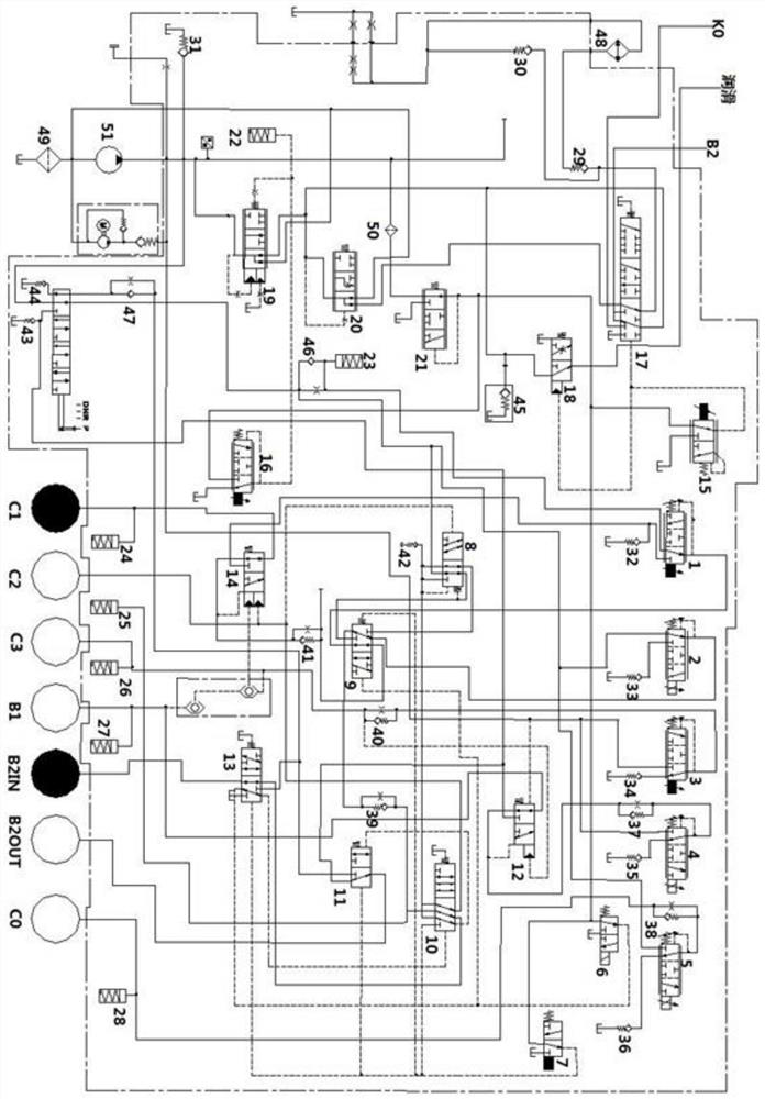
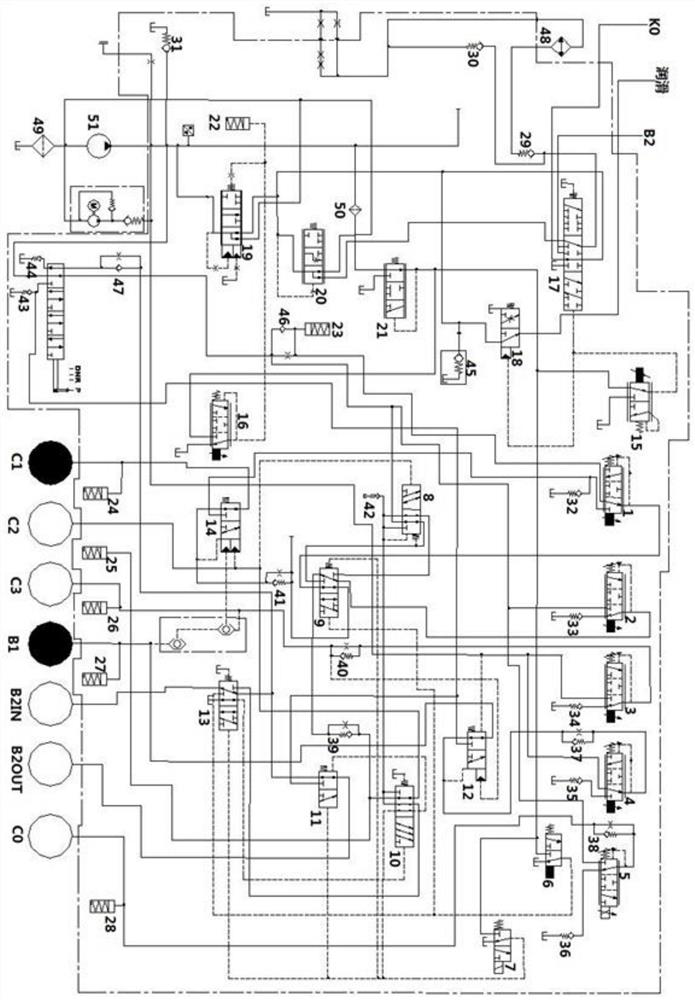
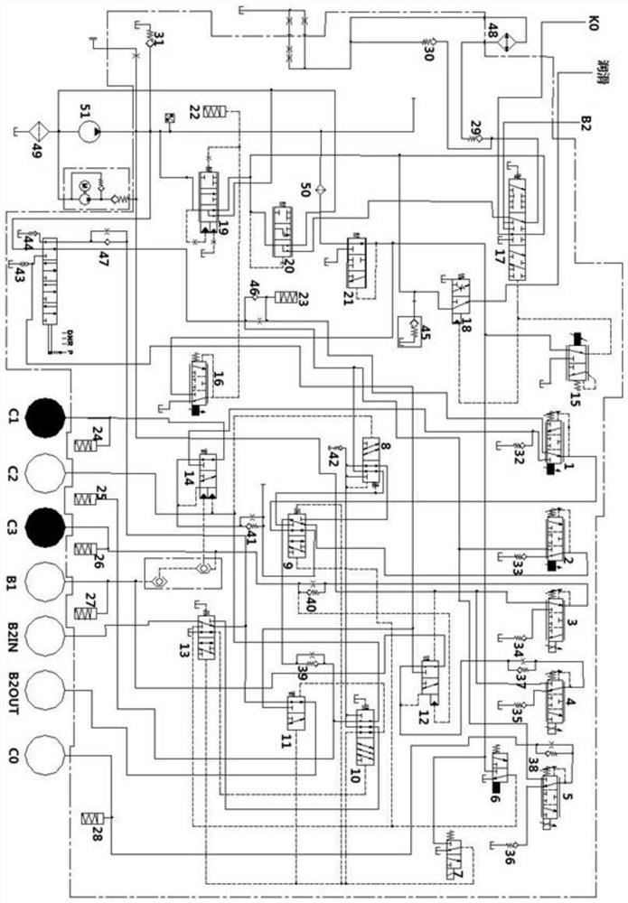
[0032] The invention will be further described in detail below with reference to the accompanying drawings:

[0033] Such as figure 1 As shown, for the hybrid transmission of the mixed transmission of the mixed transmission, including five electromagnetic commutation valves, four control electromagnetic replacement valves, twelve hydraulic replacement valves, seven accumulators, ten Nine one-way valves, an oil cooler, two oil filters, second oil filters and oil pumps.

[0034] The first electromagnetic commutation valve 1 and the second electromagnetic commutation valve 2, the fifth electromagnetic commutation valve 5, the second liquid exchange valve 9, the seventh liquid exchange valve 14, the second accumulator 23, the fourth single The valve 32 is connected to the 18th single-way valve 46.

[0035]The second electromagnetic commutation valve 2 is connected to the fifth electromagnetic commutation valve 5, the second hydraulic directional valve 9, the second accumulator 23, and...


PUM


Abstract

The invention discloses a hybrid transmission electro-hydraulic limp control oil way and method. The hybrid transmission electro-hydraulic limp control oil way comprises a main oil way body, a manual gear shifting device, a gear shifting control oil way body and a control oil way body, wherein the control oil way body is connected with the main oil way body through a twelfth hydraulic reversing valve and comprises a first control electromagnetic reversing valve and a second control electromagnetic reversing valve which are connected with each other, the first control electromagnetic reversing valve is connected with a sixth hydraulic reversing valve, the second control electromagnetic reversing valve is connected with a second hydraulic reversing valve, a third hydraulic reversing valve, a fourth hydraulic reversing valve and a sixth hydraulic reversing valve, the third hydraulic reversing valve is connected with a brake B2IN end through the sixth hydraulic reversing valve, a seventh hydraulic reversing valve is connected with a first electromagnetic reversing valve, the fourth hydraulic reversing valve is connected with a brake B2OUT end and a fifth hydraulic reversing valve, and the fifth hydraulic reversing valve is connected with a third electromagnetic reversing valve and a fourth electromagnetic reversing valve correspondingly. By means of the hybrid transmission electro-hydraulic limp control oil way and method, a hybrid transmission can still run safely under the condition that a vehicle breaks down.

Description

Technical field [0001] The present invention belongs to the field of mixing transmission, and involves a hybrid transmission of the electro-hydraulic control oil path and method. Background technique [0002] In addition to the traditional single energy vehicles in the market, mixing energy vehicles are gradually developing, and hybrid refers to at least two power sources do driving energy to drive automobiles, and the transmission is divided into several more common constituent types. : Mechanical manual transmission, automatic mechanical transmission, hydraulic automatic transmission, and stepless transmission. The liquid automatic transmission is light, simple, has good adaptive, which can greatly reduce labor intensity, and reduce the impact on the entire vehicle drive system, and the share of the current market is increasing. Its control part is mainly achieved by electro-hydraulic systems, in which the control of system pressure is related to the efficiency of the transmiss...

Claims


Application Information

Patent Timeline
Patent Type & Authority Applications(China)
IPC IPC(8): F16H61/02F16H61/40F16H61/4165
CPCF16H61/0265F16H61/40F16H61/4165
Inventor 王凯峰严鉴铂刘义朱佳兴毕乾坤赵亮徐旭冯浩成
Owner XIAN FASHITE AUTOMOBILE TRANSMISSION CO LTD
Why Eureka
Try Eureka