Optical imaging lens and imaging equipment

An optical imaging lens and lens technology, which is applied in the field of imaging lens, can solve problems such as inability to meet the needs of vehicle monitoring systems, poor recognition of long-distance targets, and unclear imaging of peripheral fields of view. It achieves small distortion and meets imaging requirements. The effect of large aperture

Active Publication Date: 2021-07-13
合肥联创光学有限公司
View PDF9 Cites 4 Cited by
  • Summary
  • Abstract
  • Description
  • Claims
  • Application Information

AI Technical Summary

Problems solved by technology

[0003] However, the existing optical lenses on the market generally have disadvantages such as poor long-distance imaging and unclear peripheral field of view imaging, which leads to poor recognition of long-distance targets and cannot meet the needs of vehicle monitoring systems.

Method used


Image

  • Optical imaging lens and imaging equipment
  • Optical imaging lens and imaging equipment
  • Optical imaging lens and imaging equipment

Examples


no. 1 example

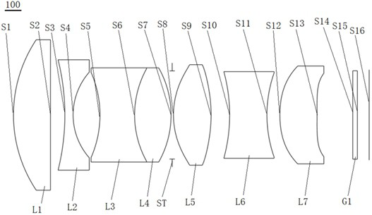
[0084] see figure 1 , which is a schematic structural view of the optical imaging lens 100 provided by the first embodiment of the present invention, the optical imaging lens 100 includes in sequence from the object side to the imaging surface along the optical axis: a first lens L1, a second lens L2, and a third lens L3, fourth lens L4, stop ST, fifth lens L5, sixth lens L6, seventh lens L7, and filter G1.

[0085] The first lens L1 has a positive refractive power, its object side S1 is a convex surface, and its image side S2 is a plane;

[0086] The second lens L2 has a negative refractive power, and its object side S3 and image side S4 are both concave;

[0087] The third lens L3 has negative refractive power, and its object side S5 and image side are both concave;

[0088] The fourth lens L4 has positive refractive power, and its object side and image side S7 are both convex surfaces, and the third lens L3 and the fourth lens L4 form an achromatic cemented lens group, th...

no. 2 example

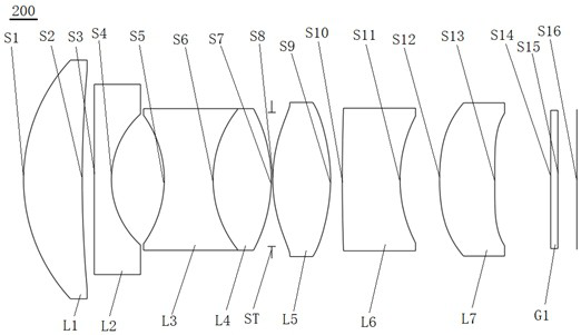
[0101] see image 3 , which is a schematic structural view of the optical imaging lens 200 provided by the second embodiment of the present invention, the optical imaging lens 200 includes in sequence from the object side to the imaging surface along the optical axis: a first lens L1, a second lens L2, and a third lens L3, fourth lens L4, stop ST, fifth lens L5, sixth lens L6, seventh lens L7, and filter G1.

[0102] The first lens L1 has positive refractive power, its object side S1 is convex, and its image side S2 is concave;

[0103] The second lens L2 has a negative refractive power, its object side S3 is a plane, and its image side S4 is a concave surface;

[0104] The third lens L3 has negative refractive power, and its object side S5 and image side are both concave;

[0105] The fourth lens L4 has positive refractive power, and its object side and image side S7 are both convex surfaces, and the third lens L3 and the fourth lens L4 form an achromatic cemented lens grou...

no. 3 example

[0118] see Figure 5 , which is a schematic diagram of the structure of the optical imaging lens 300 provided by the third embodiment of the present invention, the optical imaging lens 300 includes in sequence from the object side to the imaging surface along the optical axis: a first lens L1, a second lens L2, and a third lens L3, fourth lens L4, stop ST, fifth lens L5, sixth lens L6, seventh lens L7, and filter G1.

[0119] The first lens L1 has positive refractive power, its object side S1 is convex, and its image side S2 is concave;

[0120] The second lens L2 has negative refractive power, its object side S3 is convex, and its image side S4 is concave;

[0121] The third lens L3 has negative refractive power, and its object side S5 and image side are both concave;

[0122] The fourth lens L4 has positive refractive power, and its object side and image side S7 are both convex surfaces, and the third lens L3 and the fourth lens L4 form an achromatic cemented lens group, t...


PUM


Abstract

The invention discloses an optical imaging lens and imaging equipment. The optical imaging lens sequentially comprises a first lens, a second lens, a third lens, a fourth lens, a diaphragm, a fifth lens, a sixth lens and a seventh lens from an object side to an imaging surface along an optical axis. The first lens has positive focal power, the object side surface is a convex surface, and the image side surface is a concave surface or a plane; the second lens has negative focal power, and the image side surface of the second lens is a concave surface; the third lens and the fourth lens form an achromatic balsaming lens group, one lens is a positive focal power lens, and the other lens is a negative focal power lens; the fifth lens has positive focal power, and the object side surface and the image side surface of the fifth lens are convex surfaces; the sixth lens has negative focal power; the seventh lens has positive focal power, and the object side surface of the seventh lens is a convex surface; the seven lenses are all glass lenses, and the optical imaging lens at least comprises an aspheric lens. The optical imaging lens at least has the characteristics of large aperture, high resolution and high imaging quality.

Description

technical field [0001] The invention relates to the technical field of imaging lenses, in particular to an optical imaging lens and imaging equipment. Background technique [0002] With the vigorous development of the automobile industry, automation and in-vehicle monitoring have begun to develop rapidly. As a key component of the automatic driving assistance system, the on-board camera has also ushered in rapid development. Through the front-view, rear-view, surround-view and other on-board cameras, it can Obtain all-round information inside and outside the vehicle to help the driver make correct driving behaviors. Therefore, the adaptability of the lens to the environment and imaging stability become the safety guarantee during the driving of the car. Vehicle lenses not only need to be used in various environments such as high and low temperature conditions, acid and alkali erosion conditions, but also need to be used in low-light and dark conditions. In these occasions, t...

Claims


Application Information

Patent Timeline
Patent Type & Authority Applications(China)
IPC IPC(8): G02B13/00G02B13/18G02B1/00
CPCG02B1/00G02B13/0045G02B13/006G02B13/18
Inventor 廖宝发魏文哲王昆王克民曾吉勇
Owner 合肥联创光学有限公司
Why Eureka
Try Eureka