Separated liquid cooling system for phase change heat transfer module of data center and control method of separated liquid cooling system

A data center, separate technology, used in the use of liquid cooling for modification, cooling/ventilation/heating retrofit, electrical components, etc., can solve the problems that plague data centers, high costs, coolant leakage, etc., and reduce coolant leakage. risk, and the effect of improving the convenience of maintenance

Active Publication Date: 2021-07-13
广东液冷时代科技有限公司
View PDF3 Cites 3 Cited by
  • Summary
  • Abstract
  • Description
  • Claims
  • Application Information

AI Technical Summary

Problems solved by technology

The clustering of data centers has led to an increase in the density of servers, so heat dissipation in data centers has become a major problem that plagues the development of data centers, and liquid cooling technology has developed rapidly in recent years due to its extremely high cooling efficiency; at present, liquid cooling technology in data centers mainly Including immersion liquid cooling, direct cold plate liquid cooling and indirect cold plate liquid cooling, etc. The immersion liquid cooling is expensive and difficult to maintain due to the use of special coolant and the need for customized chassis, while the direct cold plate liquid cooling and indirect Although the cost of the cold plate liquid cooling technology is relatively low, due to the need to connect the liquid cooling pipeline during installation and maintenance, even if a self-sealing joint with certain safety is used, there will be a small amount of cooling liquid leakage during the maintenance process or due to component failure. Aging causes massive coolant leaks, which can lead to loss of electronic components and data

Method used


Image

  • Separated liquid cooling system for phase change heat transfer module of data center and control method of separated liquid cooling system
  • Separated liquid cooling system for phase change heat transfer module of data center and control method of separated liquid cooling system
  • Separated liquid cooling system for phase change heat transfer module of data center and control method of separated liquid cooling system

Examples


Embodiment Construction

[0018] In order to make the object, technical solution and advantages of the present invention clearer, the present invention will be further described in detail below in conjunction with the embodiments and accompanying drawings.

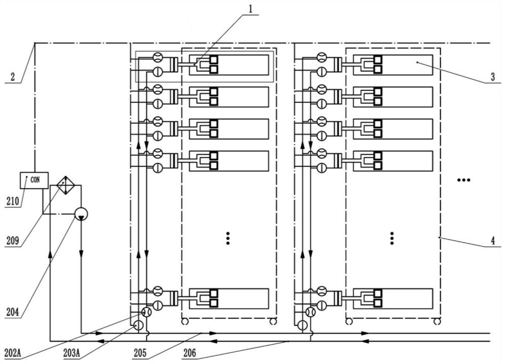
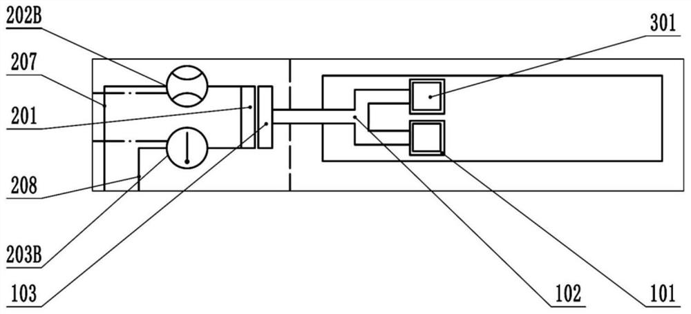
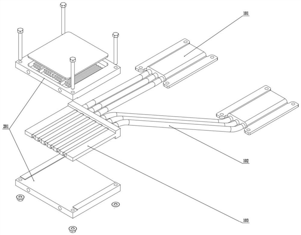
[0019] like Figure 1a and 1b As shown, it is a schematic diagram of a phase change heat transfer module separated liquid cooling system in a data center, including a phase change heat transfer module 1 and an external circulation heat exchange system 2; the phase change heat transfer module 1 is installed in a server 3, It is used to collect the heat generated by the internal processor of the server and transfer the collected heat to the heat conduction plate outside the cabinet; the external circulation heat exchange system is connected with multiple cabinets 4 in parallel to take away the heat on the heat conduction plate and discharge it into the Atmospheric environment and real-time monitoring system operation.

[0020] The external circulati...


PUM


Abstract

The invention discloses a separated liquid cooling system for a phase change heat transfer module of a data center. The system comprises a phase change heat transfer module and an external circulation heat exchange system. The phase change heat transfer module is installed in the server and used for collecting heat generated by a processor in the server and conducting the collected heat to a heat conduction plate outside the cabinet. And the external circulation heat exchange system is connected in parallel with a plurality of cabinets and is used for taking away heat on the heat conducting plate and discharging the heat into the atmospheric environment. The phase change heat transfer module and the liquid cooling system are separately designed, so that the server does not need to be connected with a liquid cooling pipeline under pressure in the installation and maintenance process, the risk of cooling liquid leakage is reduced, the maintenance convenience of the server liquid cooling system is greatly improved, and the green development of the server liquid cooling technology is promoted.

Description

technical field [0001] The invention relates to the technical field of heat dissipation and cooling of data centers, in particular to a phase-change heat transfer module-separated liquid cooling system for data centers and a control method thereof. Background technique [0002] With the development of the communication industry and electronic information technology, data centers are gradually developing towards high computing power clusters, followed by the problems of high energy consumption and heat dissipation in data centers. Since 2011, the power consumption of data centers in my country has been continuously It is expected that the total electricity consumption of data centers will exceed 260 billion kilowatt-hours in 2023. [0003] With the continuous enhancement and upgrading of computer computing power, the power of CPU and GPU used by servers continues to increase, followed by heat generation that is nearly equal to its power. The clustering of data centers has led...

Claims


Application Information

Patent Timeline
Patent Type & Authority Applications(China)
IPC IPC(8): H05K7/20
CPCH05K7/2029H05K7/208H05K7/20836
Inventor 潘敏强浮恒李超陈坚泽陈阳
Owner 广东液冷时代科技有限公司
Why Eureka
Try Eureka