Intelligent tube bending equipment
A kind of pipe bending equipment and intelligent technology, used in safety equipment, metal processing equipment, feeding devices and other directions, can solve the problems of reducing the service life of the fixture, indentation on the surface of the pipe fittings, and the diameter difference of the pipe fittings, etc., to reduce friction, Reduce the time of repeated feeding and clamping, and facilitate the effect of leak test
- Summary
- Abstract
- Description
- Claims
- Application Information
AI Technical Summary
Problems solved by technology
Method used
Image
Examples
Embodiment 1
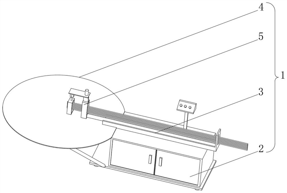
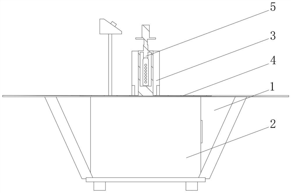
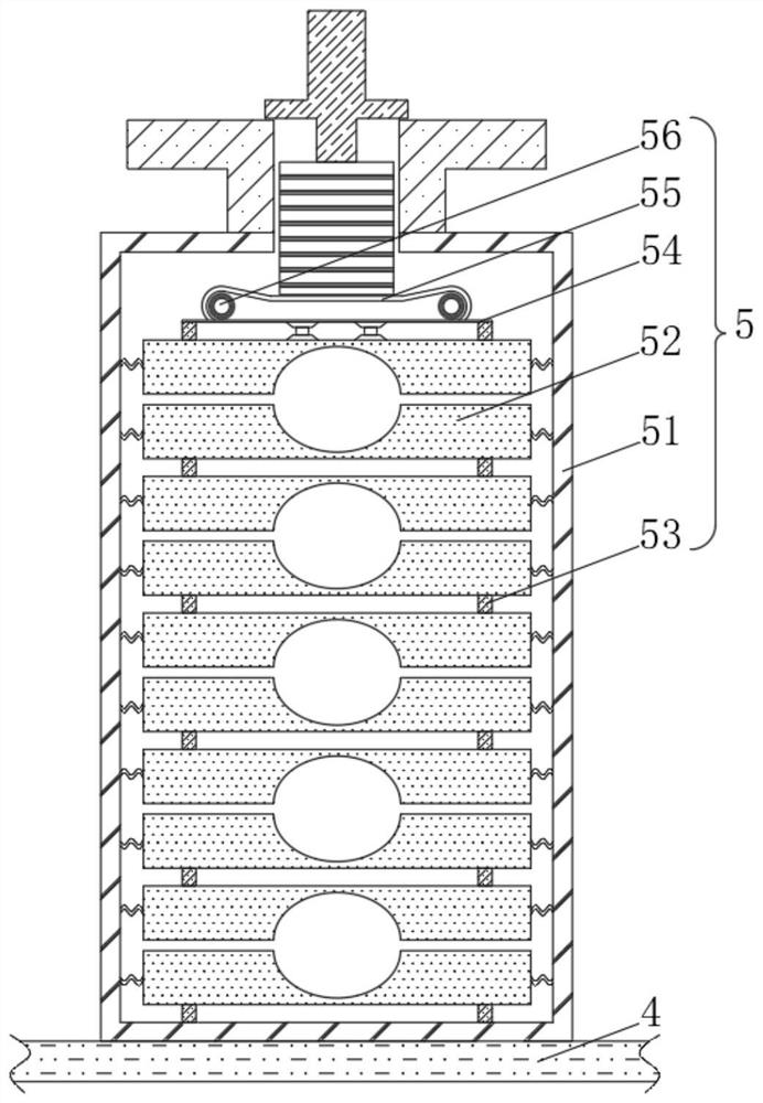
[0040] see Figure 1-4 , the present invention provides a technical solution: an intelligent pipe bending equipment, including an intelligent pipe bending equipment body 1 composed of an electric control mechanism 2, a feeding mechanism 3, a pipe bending mechanism 4 and a clamping mechanism 5, the electric control mechanism 2 and the feeding mechanism The mechanism 3 is electrically connected, the feeding mechanism 3 is slidingly connected with the pipe bending mechanism 4 through the pipe fittings, the pipe bending mechanism 4 is fixedly connected with the clamping mechanism 5, the clamping mechanism 5 includes a clamping frame 51, and the inner wall of the clamping frame 51 is slidably connected There is a clamp 52, the top of the clamp 52 is slidingly connected with a receiving block 53, the top of the receiving block 53 is fixedly connected with a receiving plate 54, the bottom of the receiving plate 54 is fixedly connected with the top of the clamp 52 through a hydraulic b...
Embodiment 2
[0046] see Figure 1-6 , On the basis of Embodiment 1, the present invention provides a technical solution: the suction pressure bag 61 includes a bag shell 611, and the inside of the bag shell 611 is provided with an expansion tube 612, and the bottom of the expansion tube 612 passes through the through hole and the breathing bag 62 The interior of the capsule shell 611 is connected with the inner wall of the capsule shell 611, and the outer connecting plate 613 and the inner connecting plate 614 are respectively fixedly connected.
[0047] The inside of the outer connecting plate 613 is fixedly connected with a one-way valve 615, and the inside of the inner connecting plate 614 is connected to the limiting plate 616 through the rotation of the resilient piece. Compression balls 617 are fixedly connected to the left side of the connecting plate 614 .
[0048] The pressing mechanism 7 includes a pressing frame 71, the top of the pressing frame 71 is fixedly connected with a w...
Embodiment 3
[0052] see Figure 1-7 , on the basis of Embodiment 1 and Embodiment 2, the present invention provides a technical solution: the anti-slip mechanism 8 includes a flexible block 81, the outside of the flexible block 81 is slidingly connected with the inside of the water-permeable block 72, and the inside of the flexible block 81 is provided with an anti-skid Pressing the sheet, the top of the flexible block 81 is fixedly connected with the friction cotton 82 , the bottom of the flexible block 81 is fixedly connected with the elastic ring 83 , and the bottom of the elastic ring 83 is fixedly connected with the top of the pressing frame 71 .
[0053]During use, when the pressing mechanism 7 presses the pipe fittings, the flexible block 81 in the anti-slip mechanism 8 is squeezed inwardly by the pipe fittings. 7. The friction between the pipe fittings prevents the pipe fittings from slipping when they are bent. The friction cotton 82 on the top of the flexible block 81 has the eff...
PUM
 Abstract
Description
Claims
Application Information
 - R&D
- Intellectual Property
- Life Sciences
- Materials
- Tech Scout
- Unparalleled Data Quality
- Higher Quality Content
- 60% Fewer Hallucinations
Browse by: Latest US Patents, China's latest patents, Technical Efficacy Thesaurus, Application Domain, Technology Topic, Popular Technical Reports.
© 2025 PatSnap. All rights reserved.Legal|Privacy policy|Modern Slavery Act Transparency Statement|Sitemap|About US| Contact US: help@patsnap.com


