
Thermally-induced fusing steel ball lock separating mechanism

A separation mechanism and steel ball lock technology, applied in motor vehicles, spaceflight equipment, spaceflight aircraft, etc., can solve the problems of poor temperature adaptability, large weight of pyrotechnics, large impact, etc., and achieve low unlocking impact and cost. Low effect with high locking and unlocking reliability

Pending Publication Date: 2021-07-16
SHANGHAI AEROSPACE SYST ENG INST
View PDF8 Cites 0 Cited by
  • Summary
  • Abstract
  • Description
  • Claims
  • Application Information

AI Technical Summary

Problems solved by technology

[0003] The purpose of the present invention is to overcome the defects and deficiencies of the prior art, and provide a thermally fused steel ball lock separation mechanism with simple structure, light weight, small unlocking impact, low cost, and wide temperature adaptability, which solves the problem of existing pyrotechnic problems. The problems of heavy product weight, large impact, poor temperature adaptability and high cost of the memory alloy separation mechanism

Method used


Image

  • Thermally-induced fusing steel ball lock separating mechanism
  • Thermally-induced fusing steel ball lock separating mechanism
  • Thermally-induced fusing steel ball lock separating mechanism

Examples


Embodiment Construction

[0029] The invention will be described in more detail hereinafter with reference to the accompanying drawings showing embodiments of the invention. However, this invention may be embodied in many different forms and should not be construed as limited to the embodiments set forth herein. Rather, these embodiments are provided so that this disclosure will be thorough and complete, and will fully convey the scope of the invention to those skilled in the art.

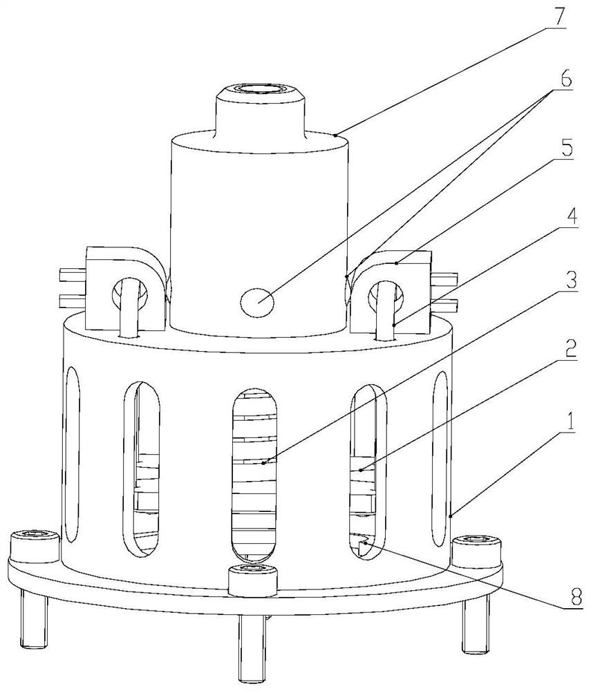
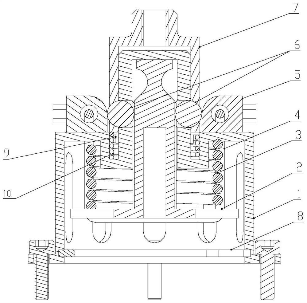
[0030] The present invention provides a thermally fused steel ball lock separation mechanism, comprising: a housing 1, an unlocking column 2, an unlocking spring 3, a restraint rope 4, a heater 5, a steel ball 6, a lock cap 7 and a retaining ring 8; its features is that

[0031] The shell 1 is a hollow cylindrical cavity at both ends, and the diameter of the upper cavity is smaller than that of the lower cavity; the outer side of the upper cavity is provided with a lock cap 7, and the upper cavity and the lock cap 7 have t...


PUM


Abstract

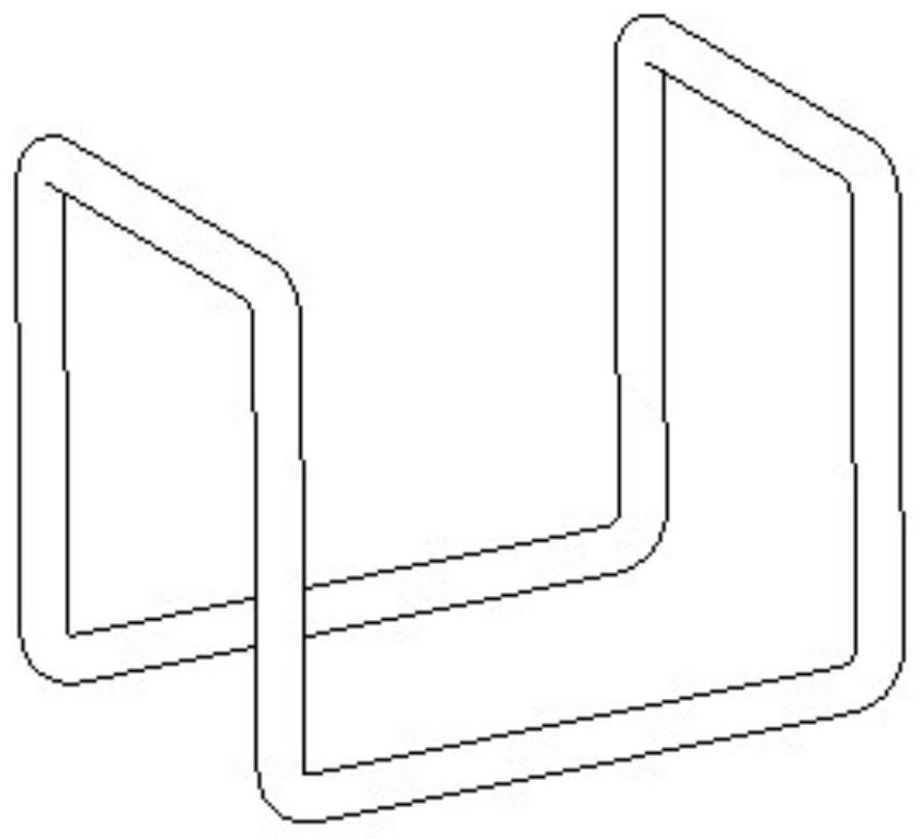
The invention discloses a thermally-induced fusing steel ball lock separating mechanism. The separating mechanism comprises a shell (1), an unlocking column (2), an unlocking spring (3), a restraining rope (4), a heater (5), a steel ball (6), a lock cap (7), a check ring (8), a limiting ring (9) and a limiting spring (10). Locking and releasing of the lock cap are achieved through the relative position relation among the shell, the unlocking column and the lock cap, an unlocking spring is installed between the unlocking column and the shell, and a restraining rope is bound between the unlocking column and the shell. The restraint rope restrains the position between the unlocking column and the shell, so that the separation mechanism is in a locked state, and the spring is in a compressed state; a heater is installed on the restraint rope, the heater is powered on, the restraint rope is fused, the unlocking spring pushes the unlocking column to move by a certain distance, and the separation mechanism is changed into an unlocking and releasing state from a locking state. The separation mechanism has the characteristics of simple structure, light weight, low impact, low cost, wide temperature adaptability, high locking and unlocking reliability and the like.

Description

technical field [0001] The invention relates to a separation mechanism, in particular to a non-pyrotechnic separation mechanism. Background technique [0002] In recent years, micro-satellites have developed rapidly. Various structural products on them, such as small expandable solar wings, antennas, etc., need to be compressed in the folded state to withstand the load of the launch section. After entering orbit, they need to be separated and released so that the products can Expand to a predetermined position or shape. Traditional spacecraft often use pyrotechnic separation devices, which have the characteristics of large carrying capacity and reliable separation, but at the same time have disadvantages such as heavy weight, high cost, and large unlocking impact, which cannot well meet the needs of microsatellites. Therefore, it is necessary to develop a lightweight, low-cost, high-performance separation mechanism. Contents of the invention [0003] The purpose of the p...

Claims


Application Information

Patent Timeline
IPC IPC(8): B64G1/64B64G1/22
CPCB64G1/645B64G1/222
Inventor 姜强詹军海崔琦峰王栋梁李舒扬
Owner SHANGHAI AEROSPACE SYST ENG INST
Learn More