Automatic discharging equipment

An automatic unloading and equipment technology, applied in the direction of conveyors, mechanical conveyors, conveyor objects, etc., can solve the problems of affecting production efficiency, high work intensity, low production efficiency, etc., to avoid manual feeding and leakage, reduce The labor intensity of workers and the effect of improving production efficiency

Active Publication Date: 2021-07-16
SHENZHEN IN CUBE AUTOMATION
View PDF6 Cites 0 Cited by
  • Summary
  • Abstract
  • Description
  • Claims
  • Application Information

AI Technical Summary

Problems solved by technology

[0002] At present, the product blanking of the pillow packaging machine is manually placed into the blister tray, which requires a lot of manpower, long working hours, high work intensity and low production efficiency.
Especially for products with irregular shapes like candy, it is inconvenient for the robot to suck it into the tray through the suction cup with the existing feeding device, and it still needs to be placed manually. Manual feeding is prone to leakage of less material, and The misplacement rate is high, which affects the production efficiency

Method used


Image

  • Automatic discharging equipment
  • Automatic discharging equipment
  • Automatic discharging equipment

Examples


Embodiment 1

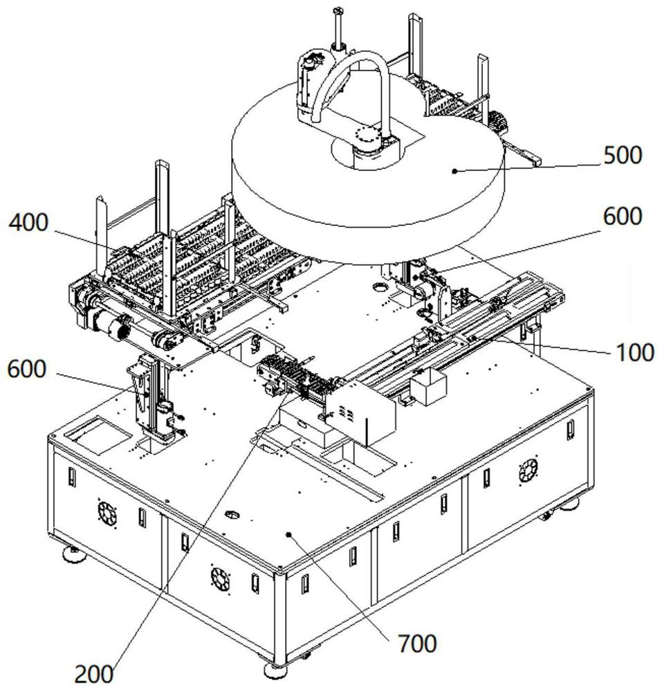
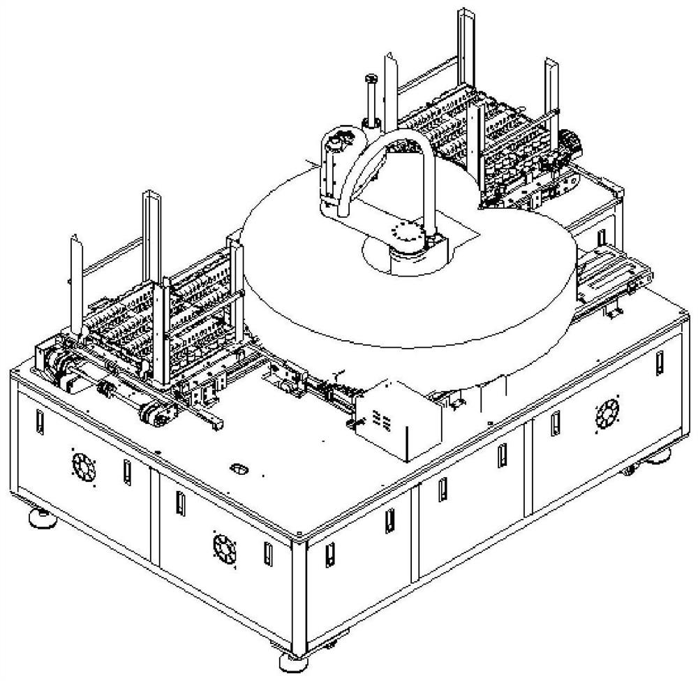
[0064] Such as Figure 1~Figure 3 As shown, a kind of automatic unloading equipment, it comprises frame 700, and described frame 700 is provided with automatic unloading device, and described automatic unloading comprises connecting conveying mechanism 100 and grasping material conveying mechanism, and described grasping material One side of the conveying mechanism is provided with a tray conveying mechanism 400, and above the grasping conveying mechanism is provided with a grasping mechanism 500; both ends of the conveying mechanism 400 are provided with a tray jacking mechanism for loading and unloading the tray 600;

[0065] The connecting conveying mechanism 100 is located on one side of the grasping conveying mechanism; the grasping conveying mechanism comprises an equidistant conveying mechanism 200 and a belt conveying mechanism 300, and the belt conveying mechanism 300 is located between the equidistant conveying mechanism 200 and the connecting conveying mechanism. B...

Embodiment 2

[0068] Such as Figure 4 and Figure 5 As shown, the tray transfer mechanism 400 includes a full tray conveyor belt 401 and an empty tray conveyor belt 402 connected to each other. One side of the full tray conveyor belt 401 is provided with a full tray palletizing mechanism 403, and the empty tray conveyer belt One side of the belt 402 is provided with an empty tray separating mechanism 404, and the trays will be divided into individual trays by the empty tray dividing mechanism 403 and placed on the empty tray conveyor belt 401. When the tray is full, the products will be sent through the full tray conveyor belt 402. To the full tray stacking mechanism 404 stacked together. Wherein, the empty tray separating mechanism 403 and the full tray stacking mechanism 404 adopt structures of the prior art.

Embodiment 3

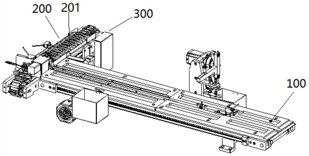
[0070] Such as image 3 , Figure 6~Figure 11 As shown, an automatic docking and unloading equipment includes a docking conveying mechanism 100 and a grabbing conveying mechanism, and the docking conveying mechanism 100 is located on one side of the grabbing conveying mechanism; the grabbing conveying mechanism includes an equidistant conveying mechanism 200 and a belt conveying mechanism 300, the belt conveying mechanism 300 is located between the equidistant conveying mechanism 200 and the docking conveying mechanism 100, the conveying direction of the equidistant conveying mechanism 200 is perpendicular to the conveying direction of the docking conveying mechanism 100, and the belt The conveying direction of the conveying mechanism 300 is the same as that of the docking conveying mechanism 100; the equidistant conveying mechanism 200 includes several product positions 201; the docking conveying mechanism 100 conveys products to one side of the belt conveying mechanism 300, ...


PUM


Abstract

The invention provides automatic discharging equipment which comprises a rack, an automatic discharging device is arranged on the rack, the automatic discharging device comprises a connection conveying mechanism and a material grabbing conveying mechanism, a material disc conveying mechanism is arranged on one side of the material grabbing conveying mechanism, and a material grabbing mechanism is arranged above the material grabbing conveying mechanism. The connection conveying mechanism is located on one side of the material grabbing conveying mechanism. The material grabbing conveying mechanism comprises an equidistant conveying mechanism and a belt conveying mechanism, the belt conveying mechanism is located between the equidistant conveying mechanism and the connection conveying mechanism, the conveying direction of the equidistant conveying mechanism is perpendicular to the conveying direction of the connection conveying mechanism, and the conveying direction of the belt conveying mechanism is the same as that of the connection conveying mechanism. The equidistant conveying mechanism comprises a plurality of product positions. By the adoption of the technical scheme, connection with a packaging machine is achieved, materials are automatically discharged and loaded into material discs, the production efficiency is greatly improved, the labor cost is saved, and the labor intensity of workers is relieved.

Description

technical field [0001] The invention relates to the technical field of automation equipment, in particular to an automatic unloading equipment. Background technique [0002] At present, the products of the pillow packaging machine are manually put into the blister tray, which requires a lot of manpower, long working hours, high work intensity and low production efficiency. Especially for products with irregular shapes like candies, using the existing feeding device, it is inconvenient for the robot to suck it into the material tray through the suction cup, and it still needs to be placed manually. The misplacement rate is high, which affects the production efficiency. Contents of the invention [0003] In view of the above technical problems, the present invention discloses an automatic unloading device, which realizes automatic unloading and loading into a tray, and improves production efficiency. [0004] To this end, the technical scheme of the present invention is: ...

Claims


Application Information

Patent Timeline
Patent Type & Authority Applications(China)
IPC IPC(8): B65G47/91B65G37/00B65G23/44
CPCB65G47/915B65G47/918B65G47/912B65G37/00B65G23/44
Inventor 关巍翟松林湛思邱鹏唐博识黄剑锋
Owner SHENZHEN IN CUBE AUTOMATION
Why Eureka
Try Eureka