
a speed reduction mechanism

A technology of reduction mechanism and body, which is applied in the direction of mechanical equipment, components with teeth, gear lubrication/cooling, etc., can solve the problems of large size of the reducer, facilitate installation and transportation, improve stability, and reduce volume Effect

Active Publication Date: 2022-04-26
WENLING LVNENG ELECTROMECHANICAL CO LTD
View PDF0 Cites 0 Cited by
  • Summary
  • Abstract
  • Description
  • Claims
  • Application Information

AI Technical Summary

Problems solved by technology

[0004] In order to improve the problem that the volume of the reducer is relatively large, the application provides a reduction mechanism

Method used


Image

  • a speed reduction mechanism
  • a speed reduction mechanism
  • a speed reduction mechanism

Examples


Embodiment Construction

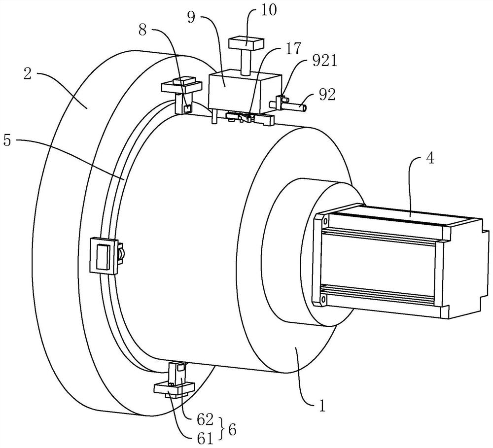
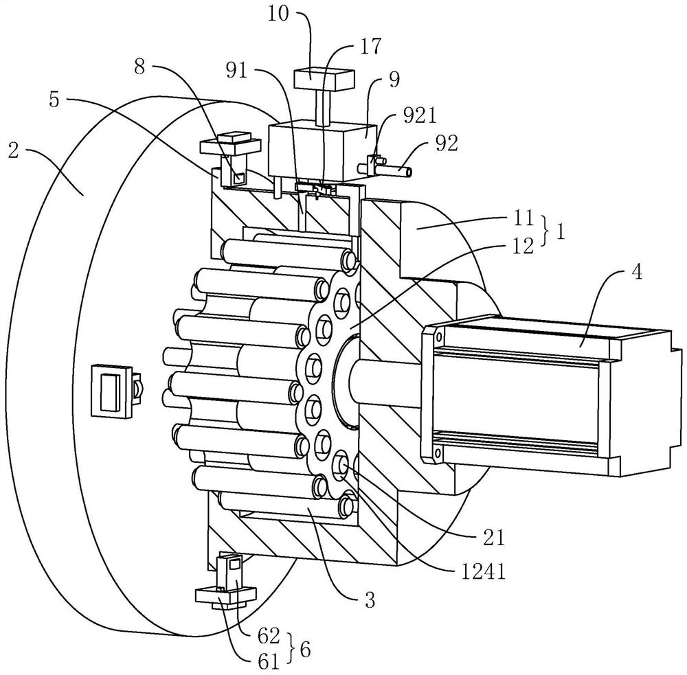
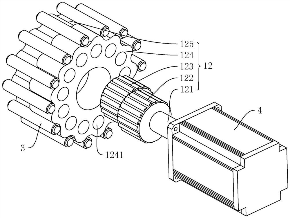
[0040] The following is combined with the attached Figure 1-8 Further elaboration of this application.

[0041] Embodiments of the present application disclose a deceleration mechanism. See Figure 1 The deceleration mechanism includes the fuselage 1 and the rotating wheel 2, the rotating wheel 2 is located on the side of the horizontal direction of the fuselage 1 and the rotating wheel 2 is connected to the fuselage 1, and the rotation axis of the rotating wheel 2 is set horizontally.

[0042] See Figure 2 and Figure 3, the fuselage 1 includes housing 11 and transmission assembly 12, the inner wall of the housing 11 is fixed with a number of needle tooth pins 3, a number of needle tooth pins 3 along the rotation axis of the rotating wheel 2 in a circumferential uniform interval distribution. Transmission assembly 12 is located in the housing 11, the transmission assembly 12 includes an input shaft 121, a first eccentric wheel 122, a second eccentric wheel 123, a first cycloidal ...


PUM


Abstract

The application relates to a reduction mechanism, which includes a machine body and a rotating wheel. The machine body includes a housing and a transmission assembly. The inner wall of the housing is provided with pin-toothed pins. The transmission assembly includes an input shaft, a first eccentric wheel, a second eccentric wheel, The first cycloidal gear and the second cycloidal gear, a number of needle rollers are arranged on the rotating wheel, and each needle roller passes through the first cycloidal gear and the second cycloidal gear, and the outer wall of the housing is provided with a limit The protruding ring is provided with a limit assembly on the rotating wheel. The first cycloidal gear and the second cycloidal gear form a cycloidal pinwheel with a number of roller needles and needle-toothed pins during the swing process to realize cycloidal pinwheel transmission, thereby driving the rotating wheel to rotate to achieve deceleration, without using excessively large gears meshing, and the axes of the first eccentric wheel, the second eccentric wheel, the first cycloidal gear, the second cycloidal gear and the rotating wheel are in the same direction, which reduces the overall volume of the body and facilitates the installation and installation of the reduction mechanism. Shipping, reducing manufacturing and shipping costs.

Description

Technical field [0001] The present application relates to the field of reducer, in particular to a reducer mechanism. Background [0002] The reducer plays a role in matching the speed and transmission torque between the prime mover and the working machine or actuator, and is widely used in modern machinery. [0003] General reducer through the size of the gear meshing way to reduce, in order to meet the needs of high power, the volume of the reducer needs to be designed to be larger, assembly and manufacturing transportation is more troublesome, the cost is higher, need to be improved. Contents of the Invention [0004] In order to improve the problem of a relatively large reducer volume, the present application provides a reducer mechanism. [0005] A deceleration mechanism provided in this application adopts the following technical solution: [0006] A deceleration mechanism, comprising a body and a rotating wheel connected to the body, the body comprises a housing and a tra...

Claims


Application Information

Patent Timeline
Patent Type & Authority Patents(China)
IPC IPC(8): F16H57/02F16H57/023F16H57/04
CPCF16H57/023F16H57/02F16H57/045F16H57/048F16H57/0449
Inventor 汪旭晨颜可富
Owner WENLING LVNENG ELECTROMECHANICAL CO LTD
Learn More