Optical pulse broadening method

A technology of optical pulse and optical coupling, which is applied in the direction of lasers, laser components, electrical components, etc.

Inactive Publication Date: 2021-07-16
UNIV OF ELECTRONIC SCI & TECH OF CHINA
View PDF6 Cites 2 Cited by
  • Summary
  • Abstract
  • Description
  • Claims
  • Application Information

AI Technical Summary

Problems solved by technology

[0006] The invention provides an optical pulse stretching method, which aims to solve the problem of narrow linewidth opt

Method used


Image

  • Optical pulse broadening method
  • Optical pulse broadening method
  • Optical pulse broadening method

Examples


Embodiment Construction

[0022] The following will clearly and completely describe the technical solutions in the embodiments of the present invention with reference to the accompanying drawings in the embodiments of the present invention. Obviously, the described embodiments are only some, not all, embodiments of the present invention. Based on the embodiments of the present invention, all other embodiments obtained by persons of ordinary skill in the art without making creative efforts belong to the protection scope of the present invention.

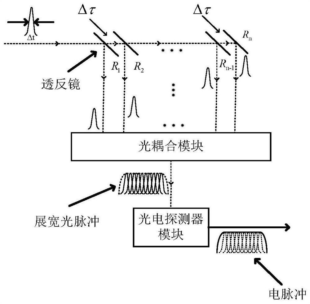
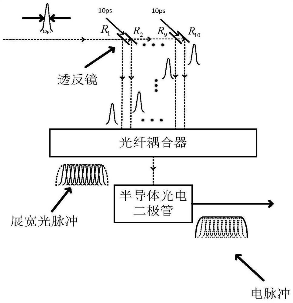
[0023] See attached figure 1 , the best embodiment of the present invention is as follows: a method of optical pulse stretching, the optical pulse is uniformly delayed and proportionally reflected / transmitted through the multi-stage optical path, and then the multi-channel optical pulse signals are combined to realize the optical pulse stretching, and then the photoelectric The detector module performs envelope detection to obtain an electric pulse signal. Sp...


PUM


Abstract

The invention belongs to the field of optical pulse signal processing, particularly relates to an optical pulse broadening method, aims to solve the problem of narrow linewidth spectrum optical pulse broadening. The optical pulse broadening method is characterized in that optical pulses are subjected to uniform delay and proportional reflection/transmission through multi-stage optical paths, then multi-path reflected optical pulse signals are combined to realize optical pulse broadening, and a photoelectric detector module is used for carrying out envelope detection to obtain an electric pulse signal. The optical pulses are transmitted to enter transflective mirrors with specific reflectivity, the distances between the adjacent transflective mirrors are equal, the corresponding delays are further equal, the optical pulse is transmitted to enter the optical coupling module for the same distance after being reflected each time, multiple paths of optical pulses are arranged and combined on a time domain after being coupled to realize optical pulse broadening, and the electric pulse signal is obtained through the photoelectric detection module. The optical pulse broadening method is further suitable for broadening wide spectrum pulse signals.

Description

technical field [0001] The invention belongs to the field of optical pulse signal processing, in particular to an optical pulse stretching method. Background technique [0002] Optical pulse processing technology is widely used in optical signal processing, optical sensor network, all-optical network and other fields. Receive processing. At present, the following two methods are used for more optical pulse stretching methods: [0003] 1. Using optical fiber group velocity dispersion, the group velocity of different wavelength components of the optical pulse is different, thus forming different transmission delays in the time domain, and finally broadening the optical pulse. The amount of optical pulse broadening is determined by the spectral width of the optical pulse, fiber dispersion coefficient and length. If the spectral width is 10nm and the dispersion coefficient is 16ps / nm.km, then a 2km dispersion fiber can achieve 320ps optical pulse broadening. The advantage of ...

Claims


Application Information

Patent Timeline
IPC IPC(8): H01S3/00H01S3/11
CPCH01S3/0057H01S3/11
Inventor 邱琪刘洁史双瑾范志强苏君
Owner UNIV OF ELECTRONIC SCI & TECH OF CHINA
Why Eureka
Try Eureka