Control method and control device of flyback converter

A technology of a flyback converter and a control method, which is applied in output power conversion devices, control/regulation systems, conversion of DC power input to DC power output, etc., can solve problems such as flyback converter losses and reduce switching. Loss, cost reduction, simple control effect

Active Publication Date: 2021-07-16
MORNSUN GUANGZHOU SCI & TECH
View PDF8 Cites 0 Cited by
  • Summary
  • Abstract
  • Description
  • Claims
  • Application Information

AI Technical Summary

Problems solved by technology

[0009] In view of this, the purpose of the present invention is to provide a control method and control device for a flyback converter, which mainly solves the loss problem of the existing flyback converter working under high-frequency and high-voltage conditions. At the same time, the invention is applicable to output current Smaller low power applications and can save costs

Method used


Image

  • Control method and control device of flyback converter
  • Control method and control device of flyback converter
  • Control method and control device of flyback converter

Examples


no. 1 example

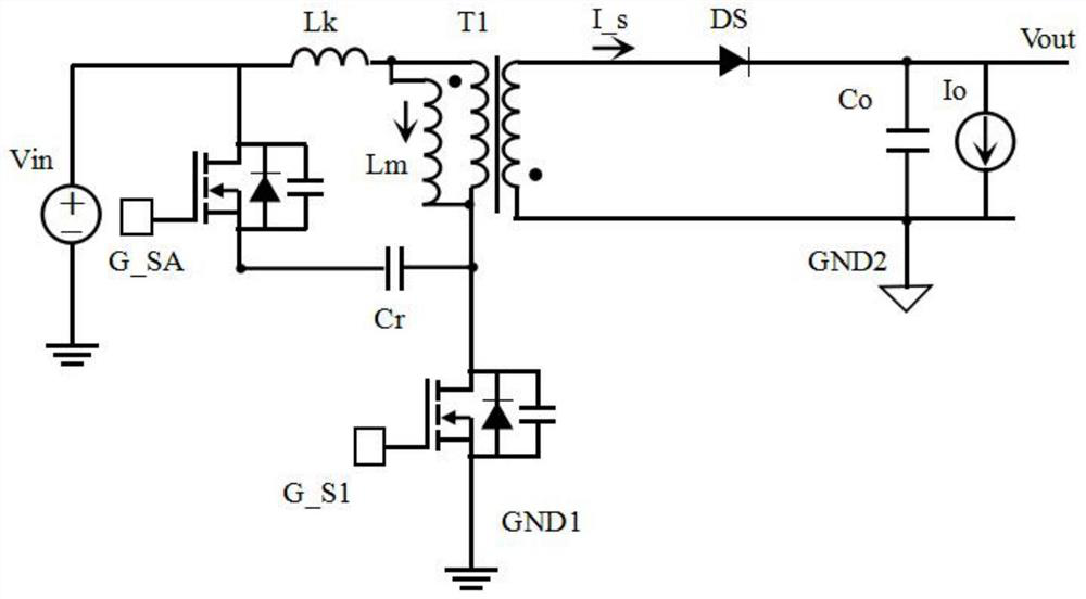
[0075] image 3 It is the circuit schematic diagram of the flyback converter of the first embodiment of the present invention, image 3 The flyback converter comprises a primary side main power switch unit 250, a secondary side switch rectifier unit 230, a transformer T1, a clamp circuit 204, a feedback circuit 243, an output capacitor Co and the control device of the present invention; the control device includes a primary side The controller 240, the isolation circuit 241, the secondary side controller 242 and the feedback circuit 243; the primary side controller 240 detects the input voltage to generate the input voltage detection signal Vin_s, and the feedback circuit 243 detects the output power to generate the output power detection signal FB and outputs it to the primary side The controller 240, the primary side controller 240 generates a control signal SW according to the input voltage detection signal Vin_s and the output power detection signal FB, and controls the open...

no. 2 example

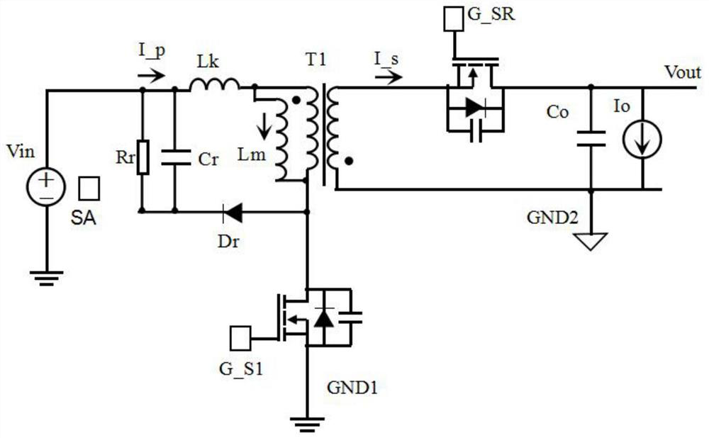
[0096] Figure 6 It is the circuit schematic diagram of the flyback converter of the second embodiment of the present invention, Figure 6 The difference from the first embodiment is that the second embodiment judges the working mode of the flyback converter through two signals, namely, the input voltage detection signal Vin_s and the output power detection signal FB.

[0097] Such as Figure 7 Shown is the flow chart of the switching method of the second implementation of the present invention: when the input voltage detection signal Vin_s is greater than or equal to the first threshold Vth_vin1, and the output power detection signal FB is greater than or equal to the second threshold Vth_vo1, the flyback converter works at the first threshold A working mode; otherwise, when the input voltage detection signal Vin_s is smaller than the first threshold Vth_vin1 or the output power detection signal FB is smaller than the second threshold Vth_vo1_, the flyback converter works in...

Embodiment 2

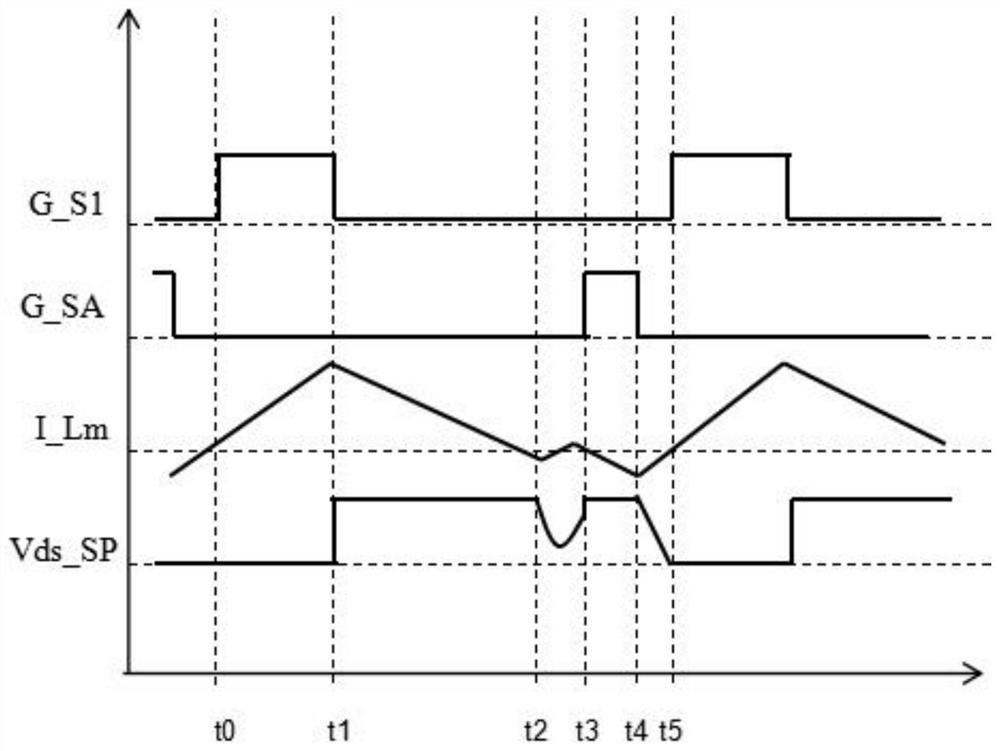
[0098] Embodiment 2 The schematic diagrams of the waveforms of the first working mode and the second working mode are the same as those in the first embodiment, and each cycle in the first working mode is also divided into four stages, which are the same as those in the first embodiment, and will not be repeated here.


PUM


Abstract

The invention provides a control method and a control device of a flyback converter. The flyback converter is judged to work in a first working mode or a second working mode by detecting an input voltage signal or detecting the input voltage signal and output power. Through mode switching, according to different input voltages or different input voltages and output loads, cost and efficiency under a high-frequency application occasion can be taken into consideration, and compared with a traditional flyback mode, the scheme has the advantages that an active clamping tube of a primary side is reduced, so that cost is reduced; and meanwhile, quasi-resonance control can be realized under low input voltage, and ZVS can be realized under high input voltage and different output powers, so that the switching loss is reduced, and the efficiency is improved.

Description

technical field [0001] The invention relates to the field of switching converters, in particular to a control method and a control device for a flyback converter. Background technique [0002] Flyback converters are widely used in low-power switching power supplies. With the development of high frequency and small size, the proportion of switching losses of flyback converters has increased significantly, especially under specific high-voltage conditions. [0003] The quasi-resonant flyback converter (QRFlyback) can realize the valley conduction of the main power switching unit on the primary side and reduce switching loss. Its circuit cost is low and the control method is simple. It is currently the most popular in low-power switching power supply applications. Topology. However, in high-frequency applications, although the quasi-resonant flyback converter can achieve valley conduction, the switching loss is also increasing at high-voltage input, which will seriously affect...

Claims


Application Information

Patent Timeline
IPC IPC(8): H02M3/335H02M1/08
CPCH02M3/33592H02M1/08H02M1/083Y02B70/10
Inventor 刘峻宇李健王海洲
Owner MORNSUN GUANGZHOU SCI & TECH
Why Eureka
Try Eureka