Clinical photoacoustic imaging system

A technology of photoacoustic imaging and data acquisition system, which is applied in the directions of acoustic wave diagnosis, infrasonic wave diagnosis, ultrasonic/sonic wave/infrasonic wave diagnosis, etc. It can solve problems such as changing the imaging surface, affecting the imaging result, and easy shaking of the probe

Pending Publication Date: 2021-07-23
天津朗原科技有限公司 +1
View PDF0 Cites 0 Cited by
  • Summary
  • Abstract
  • Description
  • Claims
  • Application Information

AI Technical Summary

Problems solved by technology

If the probe is only held by hand, the probe is easy to shake, causing changes in the imaging plane, thus affecting the imaging results

Method used


Image

  • Clinical photoacoustic imaging system
  • Clinical photoacoustic imaging system
  • Clinical photoacoustic imaging system

Examples


Embodiment 1

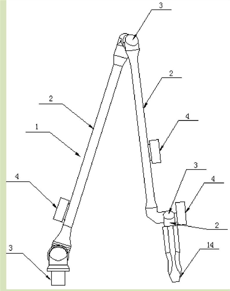
[0051] In this embodiment, the three joint light guiding arm is an example, such as figure 1 As shown, only the first angular measuring device 4 is mounted on the light guiding arm section 2, and each light guiding arm section 2 is rotated, the first angular measuring device 4 is rotated, the first angular measuring device 4 outputs the inclination angle The change value is the angular value rotated for the corresponding light guiding arm segment 2 and the photonic imaging probe 14.

Embodiment 2

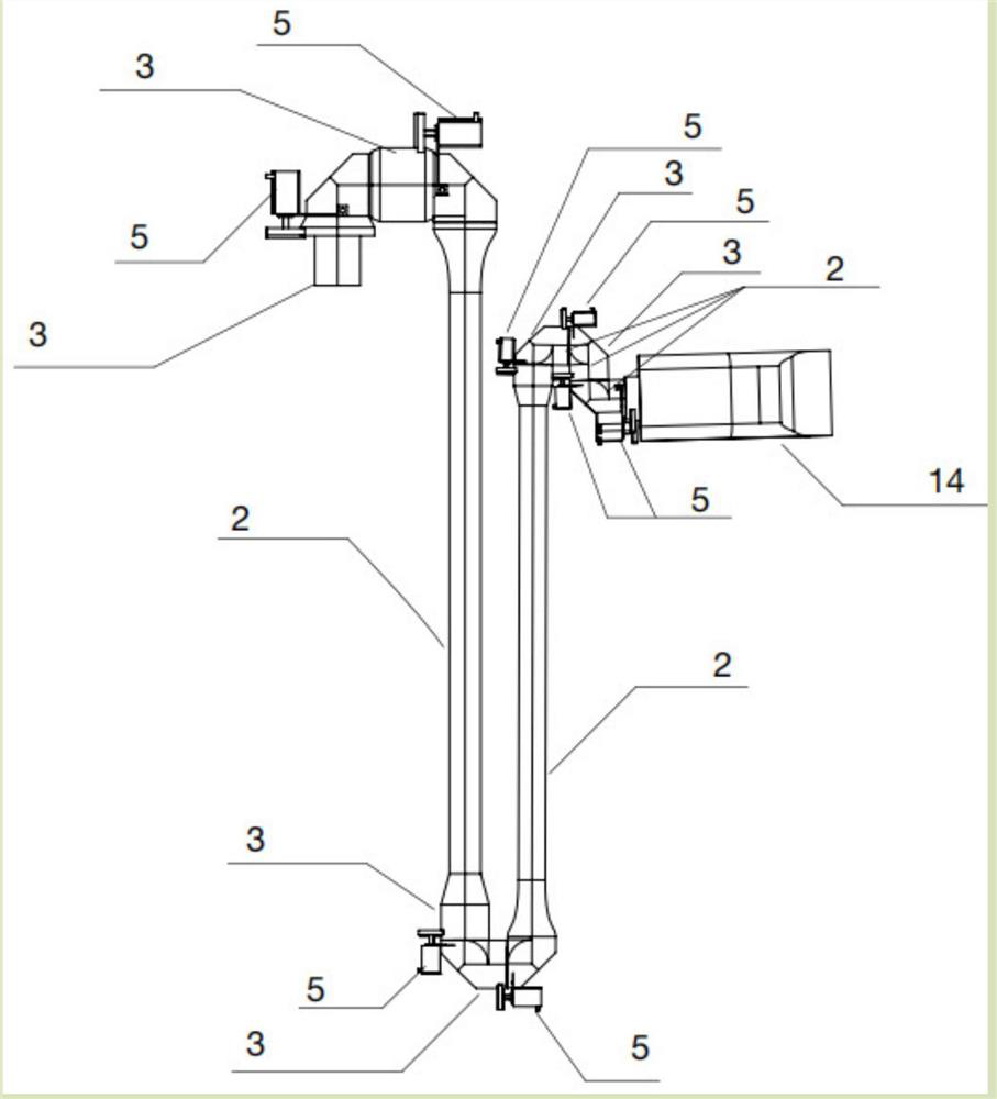
[0053] In the present embodiment, the seven-step light guides as an example, such as figure 2 As shown, only the second angle measuring device 5 is mounted on the joint shaft 3, when the light guiding arm section 2 is rotated, the joint shaft 3 simultaneously rotates, and rotates the measurement roller 7 on the second angle measuring device 5 on which it is rubbed. The rotation information is collected, thereby calculating the rotational angle of the respective light guiding arms 2 and the photonic imaging probe 14.

Embodiment 3

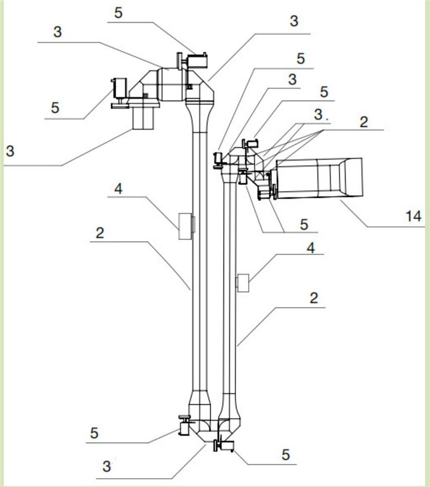
[0055] In the present embodiment, the seven-step light guides as an example, such as image 3 As shown, the first angular measuring device 4 is mounted on any two light guides 2, respectively, and the second angular measuring device 5 is mounted on any five joint shaft 3, and the joint axis is attached to the light guiding arm 3 Simultaneously rotate, the light guiding arm section 2 of the first angle measuring device 4 can drive the first angular measuring device 4 on which the first angular measuring device 4 outputs the inclination change value of the output of the corresponding light guiding arm. 2 The angle value of the rotation, the joint shaft 3 mounted with the second angle measuring device 5 rotates through the measurement roller 7 on the second angular measuring device 5 thereon, and collects the rotation information, thereby calculating the corresponding guide. The angle of rotation of the light arm section 2 and the photonic imager probe 14;

[0056] Optionally, it is O...


PUM


Abstract

The invention discloses a clinical photoacoustic imaging system. The system comprises a light guide arm and a probe. The light guide arm is used as a main component for transmitting light energy, comprises a plurality of arm sections and can rotate by any angle by taking the connected joint shaft as a shaft. A rotation angle measuring device is arranged on the light guide arm section or at the joint and can measure the rotation angle value of each arm section. The probe can be positioned in real time by combining the arm length and the probe length, so that three-dimensional photoacoustic imaging is realized. A joint locking device is arranged at a joint shaft, so that the position of the probe can be locked, and the imaging quality is improved. A gyroscope and an accelerometer are arranged in the probe and can assist in positioning. The exterior of an ultrasonic module is coated with a metal-plated compound film, so that electrical and optical noise can be shielded.

Description

Technical field [0001] The present disclosure generally relates to the field of photonic sound imaging, and more particularly to a clinical photonic imaging system. Background technique [0002] In order to facilitate surgeons to see the position of the surgical instrument and lesion in the human group by the image navigation, the imaging modal modal modes in the past clinically used in the past, thereby achieving minimally invasive surgery and non-invasive diagnosis, reducing the pain of patients. However, in view of the ultrasonic reflection characteristics of the ultrasound image recorded, it is limited, and the structural contrasts provided by this imaging method are also limited, such as the lack of reliable recognition ability of lymph nodes in biological tissues. . [0003] Thereafter, in order to improve the reliable recognition ability of the tissue, the photonic image is rapidly developed due to its characteristics of non-invasive, non-ionization, non-invasive imaging. ...

Claims


Application Information

Patent Timeline
IPC IPC(8): A61B5/00A61B8/00
CPCA61B5/0095A61B8/4209A61B8/4245A61B8/4444
Inventor 邓翰迪王小军马骋王铉皓方晨雨段汉卿高渐攀霍浩铭
Owner 天津朗原科技有限公司
Why Eureka
Try Eureka