Ammonia spraying structure and reactor

A nozzle and straight edge technology, applied in the field of flue gas denitrification, can solve the problems of small effective cross-section and large cross-sectional area

Pending Publication Date: 2021-07-23
CHINA HUADIAN ENG +1
View PDF0 Cites 0 Cited by
  • Summary
  • Abstract
  • Description
  • Claims
  • Application Information

AI Technical Summary

Problems solved by technology

[0004] Therefore, the technical problem to be solved by the present invention is to overcome the defect that the ammonia injection structure occupies a large cross-sectional area of ​​the flue in the pri...

Method used


Image

  • Ammonia spraying structure and reactor
  • Ammonia spraying structure and reactor
  • Ammonia spraying structure and reactor

Examples


Embodiment 1

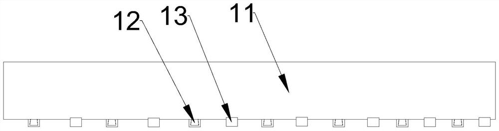
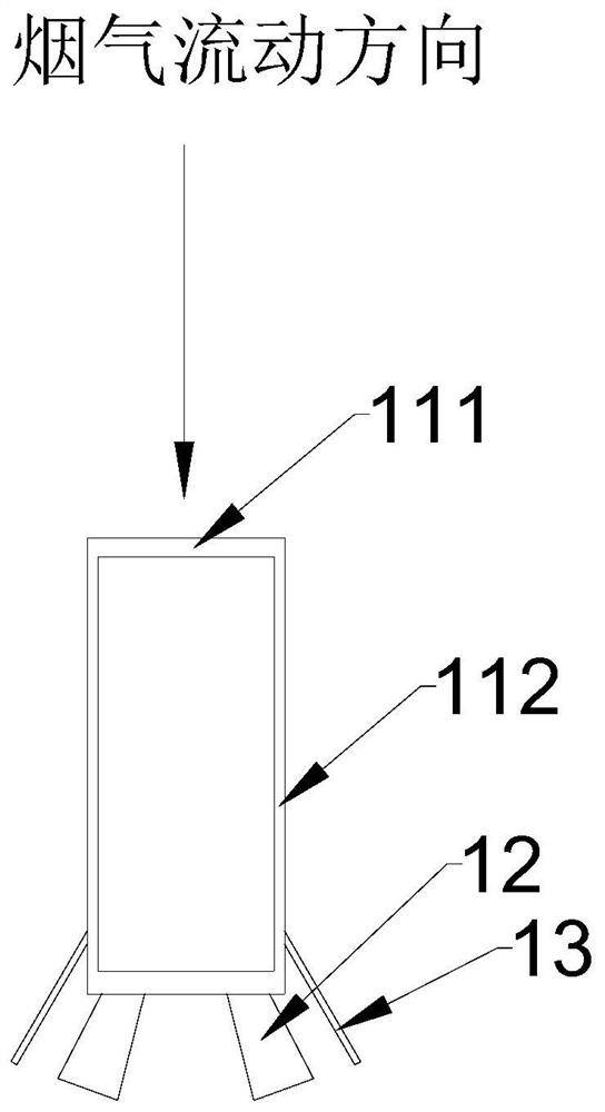
[0034] Such as Figure 1 to Figure 3 As shown, an ammonia injection structure 1 is provided in this embodiment, including an ammonia injection pipe 11, a plurality of nozzles 12 and a plurality of protective plates 13, and the cross section of the ammonia injection pipe 11 includes at least one Straight side 111, and at least one connecting side 112 that is connected with described straight side 111 and encloses a closed space together with described straight side 111; The projection of each described connecting side 112 on described straight side 111 all falls Within the range of the straight side 111, the farthest extension distance of the cross-section in the flue gas flow direction is greater than or equal to the width of the straight side 111; the ammonia injection pipe 11 includes an injection inlet and a plurality of injection outlets; A plurality of nozzles 12 is a tubular structure, one end communicates with the injection outlet, and the other end extends along the di...

Embodiment 2

[0059] In this example, if Figure 4 As shown, a reactor 2 is provided, including an inlet flue 3 and a plurality of the above-mentioned ammonia injection structures 1 , and a plurality of the ammonia injection structures 1 are distributed in the inlet flue 3 . A deflector 4 is arranged inside the inlet flue 3 . Preferably, a plurality of ammonia injection structures 1 are divided into at least two groups along the flue gas flow direction, and each group of ammonia injection structures 1 is evenly distributed on a plane perpendicular to the flue gas flow direction, and two adjacent groups of ammonia injection structures 1 are distributed in the flue gas flow direction. staggered in the direction of flow.

[0060] The ammonia injection structure 1 includes an ammonia injection pipe 11, a plurality of spray nozzles 12 and a plurality of protective plates 13, and the cross section of the ammonia injection pipe 11 includes at least one straight edge 111 perpendicular to the flue ...


PUM


Abstract

The invention relates to the technical field of flue gas denitration, in particular to an ammonia spraying structure and a reactor. The ammonia spraying structure comprises an ammonia spraying pipe, a plurality of nozzles and a plurality of protection plates, the cross section of the ammonia spraying pipe comprises at least one straight edge perpendicular to the flue gas flowing direction and at least one connecting edge connected with the straight edge, and the connecting edge and the straight edge jointly define a closed space; the projection of each connecting edge on the straight edge falls within the range of the straight edge, and the farthest extension distance of the cross section in the flue gas flowing direction is larger than or equal to the width of the straight edge; the ammonia spraying pipe comprises a spraying inlet and a plurality of spraying outlets; the nozzles are of tubular structures, one ends of the nozzles communicate with the spraying outlets, and the other ends of the nozzles extend in the flowing direction of the flue gas; and the plurality of protection plates are connected to the ammonia spraying pipe, and each protection plate is matched with one nozzle and is suitable for preventing the nozzle from being blocked. Compared with a traditional ammonia spraying structure, the ammonia spraying structure occupies a small cross sectional area of the flue.

Description

technical field [0001] The invention relates to the technical field of flue gas denitrification, in particular to an ammonia injection structure and a reactor. Background technique [0002] At present, the power plant is undergoing a new round of ultra-low emission transformation projects, which involves the transformation and replacement of a large number of flue gas denitrification devices. In the modified or newly built denitrification reactor, multiple ammonia injection structures are usually installed in the vertical section of the reactor to inject ammonia gas, and the injected ammonia gas reacts with flue gas in the reactor to denitrify nitrogen oxides. The ammonia injection structure is generally made of circular steel pipes, and there are multiple injection ports crossed on the circular steel pipes. Each injection port is welded with nozzles at different angles, and ammonia gas is injected at different angles through the nozzles. [0003] Multiple ammonia injection...

Claims


Application Information

Patent Timeline
IPC IPC(8): B01D53/76B01D53/56
CPCB01D53/56B01D53/76B01D2251/2062B01D2258/0283
Inventor 夏怀鹏白永锋吴冲王凯亮汪洋李伟
Owner CHINA HUADIAN ENG
Why Eureka
Try Eureka