
Electrophotographic device and density Control method thereof

A technology of electrophotography and density control, applied in the direction of electrography, electrorecording process using charge pattern, equipment of electrorecording process applying charge pattern, etc., can solve problems such as damage, infrequent cleaning, etc. reduction, better prints, and avoidance of cleaning operations

Inactive Publication Date: 2003-12-17
SAMSUNG ELECTRONICS CO LTD
View PDF0 Cites 0 Cited by
  • Summary
  • Abstract
  • Description
  • Claims
  • Application Information

AI Technical Summary

Problems solved by technology

However, it is best to clean these windows infrequently due to possible damage during disassembly and reassembly of these parts

Method used


Image

  • Electrophotographic device and density Control method thereof
  • Electrophotographic device and density Control method thereof
  • Electrophotographic device and density Control method thereof

Examples


Embodiment Construction

[0072] The tasks, features and advantages of the present invention described above will be more clearly understood through some preferred embodiments with reference to the accompanying drawings.

[0073] Some preferred embodiments of the density device of the electrophotographic device according to the present invention will be described in detail below.

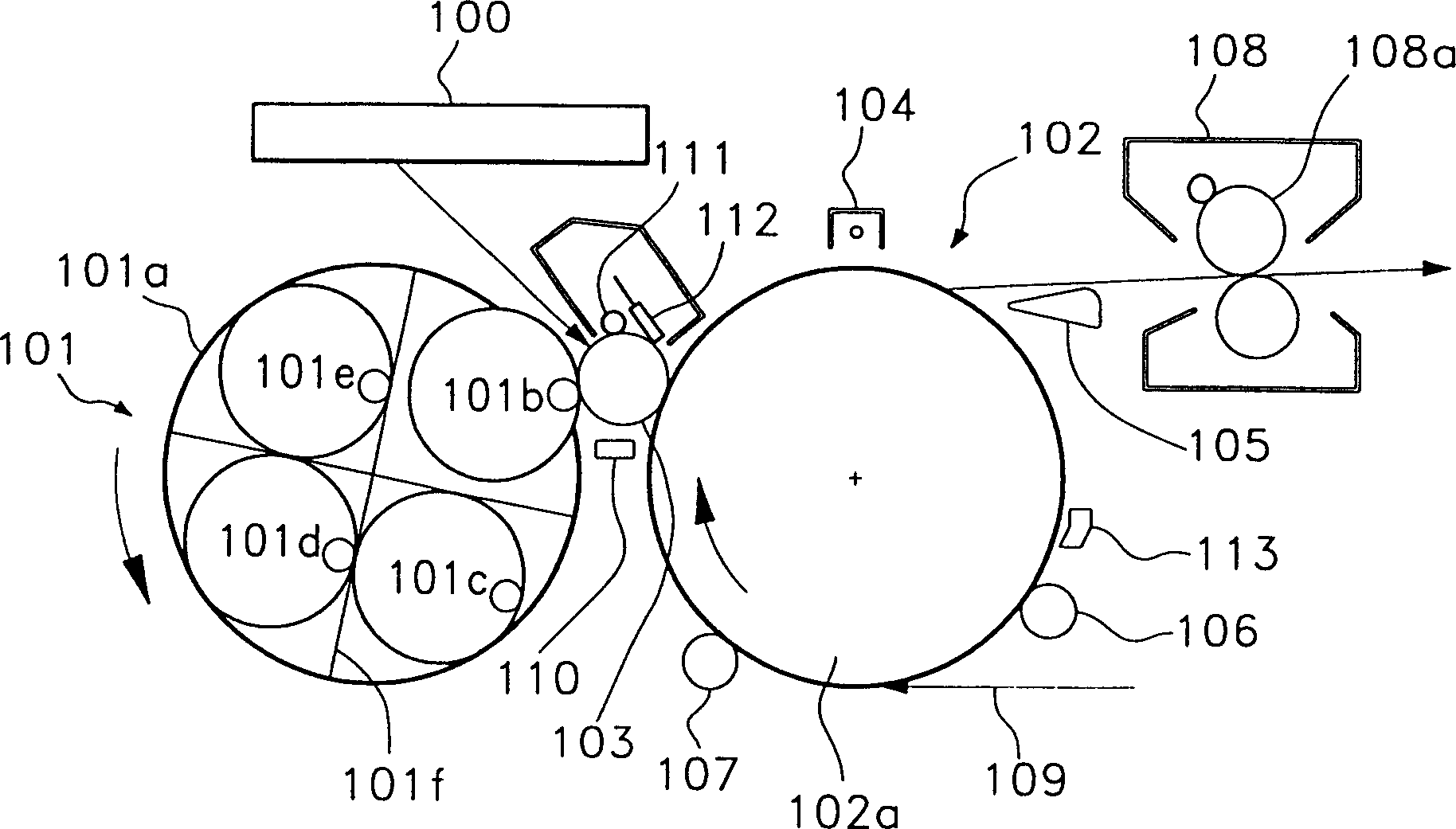
[0074] The density control device of the present invention can be applied to various electrophotographic devices using electrophotographic developing methods. it's here, Figures 5 to 7 Applied to various electrophotographic devices using electrophotographic developing methods not limited to a specific density detection device.

[0075] A color laser printer using the electrophotographic developing method will be described below.

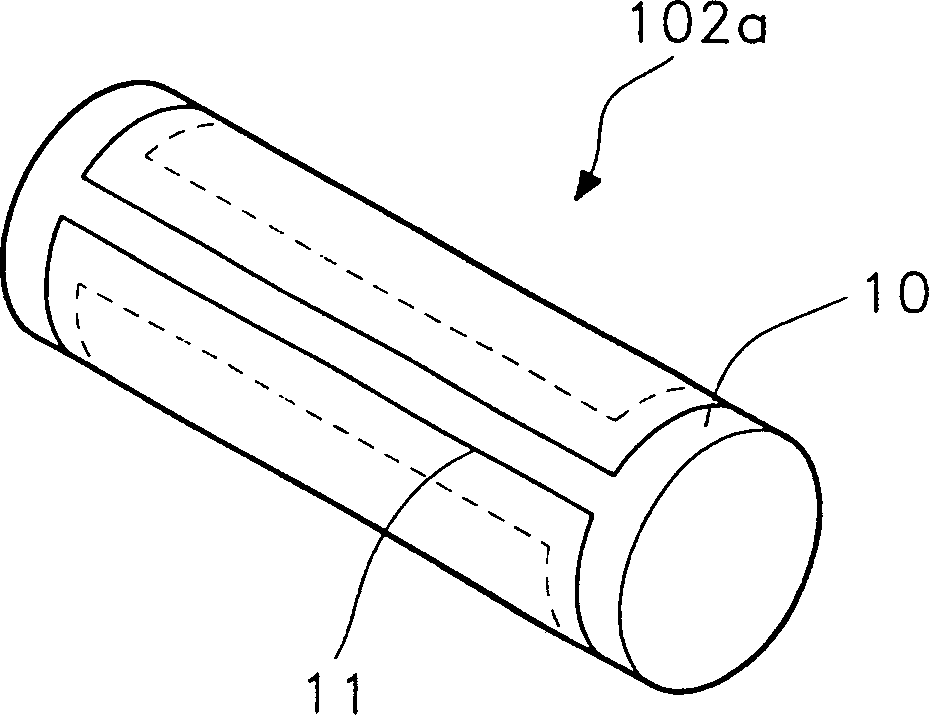
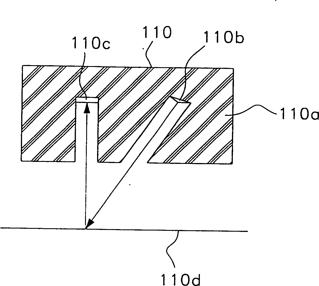
[0076] Figure 5 is a structural diagram for explaining the position of a density control device in a color laser printer using the electrophotographic developing method according to the presen...


PUM


Abstract

An electrophotographic device and a density control method are disclosed. In the apparatus such as a color laser beam printer and a copier using an electrophotographic developing method, the invention obtains an optimum print output regardless of the remaining toner or other contamination by locating a density control module inside of a transfer body, and by providing a transparent window in a dielectric sheet formed on the exterior surface of the transfer body.

Description

technical field [0001] The present invention relates to an electrophotographic apparatus, such as a color laser printer and a color copying machine using an electrophotographic developing method, and more particularly, to an electrophotographic apparatus capable of accurately detecting a color tone formed on the surface of a photoreceptor in the entire light area. An electrophotographic device and a density control method thereof for obtaining an optimum printout of the density of an agent image. Background technique [0002] Generally, in an image forming apparatus using an electrophotographic developing method such as a color copier, a color printer, etc., a charge roller is rotated and uniformly charges a photoreceptor on the outer periphery of a photoreceptor drum with a high voltage. [0003] Moreover, the charged photoreceptor on the outer periphery of the photosensitive drum forms an electrostatic latent image by means of light emitted from a light source of an exposu...

Claims


Application Information

Patent Timeline
Patent Type & Authority Patents(China)
IPC IPC(8): G03G15/00G03G15/01G03G15/04G03G15/043G03G15/06G03G15/08G03G15/16
CPCG03G15/5041G03G15/01G03G2215/00063G03G2215/0177G03G2215/00042G03G15/5033G03G15/08
Inventor 金南龙
Owner SAMSUNG ELECTRONICS CO LTD
Learn More