Pushing device for injection molding machine and injection molding system thereof

A technology of a pushing device and an injection molding machine, applied in the field of injection molding machines, can solve the problems of reducing the service life of the screw pushing device, increasing the working load of the heating ring, and easily blocking the discharge port, etc., so as to improve the uniform heating effect and waste heat. Utilize the effect of reasonable flow direction and improve heat exchange efficiency

Inactive Publication Date: 2021-07-23
柏松
View PDF1 Cites 1 Cited by
  • Summary
  • Abstract
  • Description
  • Claims
  • Application Information

AI Technical Summary

Problems solved by technology

[0004] But there are still many deficiencies in the prior art, such as: 1, the heating ring is inserted on the screw pushing device to heat the plastic, the heating ring can only heat the plastic outside the screw pushing device, and the plastic inside the screw pushing device It solidifies in advance due to insufficient heat, and it is easy to block the discharge port; 2. The heat will be lost during the transfer process, and the plastic stored in the storage barrel is more than the plastic in the screw pusher device, a

Method used


Image

  • Pushing device for injection molding machine and injection molding system thereof
  • Pushing device for injection molding machine and injection molding system thereof
  • Pushing device for injection molding machine and injection molding system thereof

Examples


Embodiment Construction

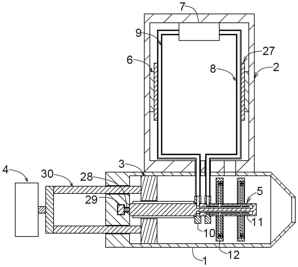
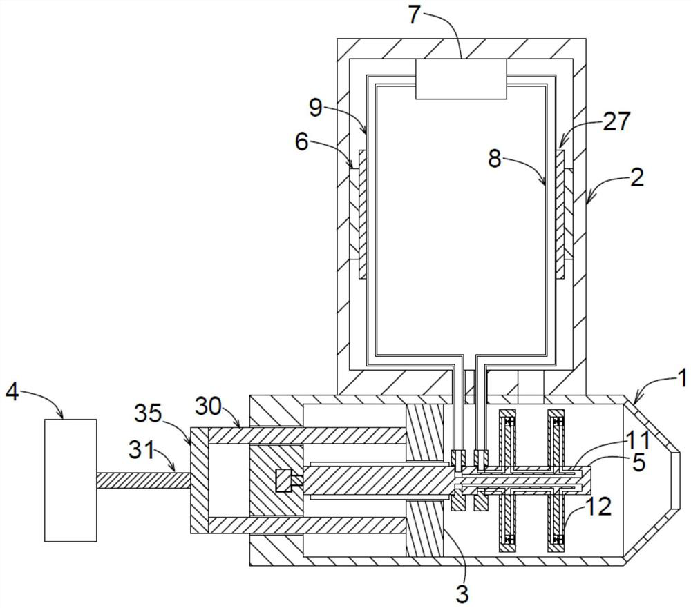
[0036] The following will clearly and completely describe the technical solutions in the embodiments of the present invention with reference to the accompanying drawings in the embodiments of the present invention. Obviously, the described embodiments are only some, not all, embodiments of the present invention. Based on the embodiments of the present invention, all other embodiments obtained by persons of ordinary skill in the art without making creative efforts belong to the protection scope of the present invention.

[0037] see Figure 1-9 , the present invention provides a technical solution:

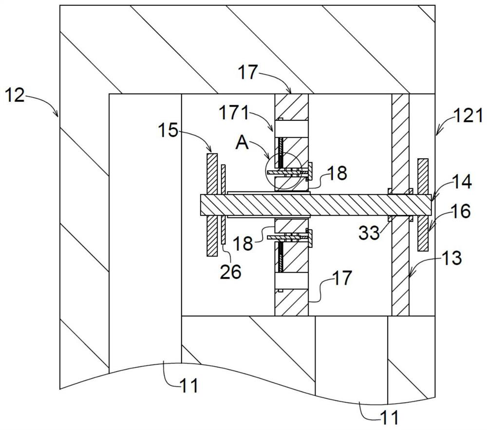
[0038] A pusher device for an injection molding machine, comprising a connected pusher barrel 1 and a storage barrel 2, the injection molding material enters the pusher barrel 1 from the stocker barrel 2 through the connection, the pusher barrel 1 is open at one end, and A push plate 3 is slidably connected to the push barrel 1, and the push plate 3 slides to push the injection mo...


PUM


Abstract

The invention discloses a pushing device for an injection molding machine and an injection molding system thereof. The pushing device comprises a pushing barrel and a storage barrel, a pushing plate is slidably connected into the pushing barrel, a rotating rod movably penetrates through the interior of the pushing plate, a plurality of heating plates are fixedly connected to the rotating rod, a heat transfer assembly comprises a gas conveying pipe, a heat exchange agent circulating pump and a liquid return pipe which are sequentially communicated, a heating groove channel is communicated between the rotating rod and the heating plates, the two ends of the heating groove channel communicate with the gas conveying pipe and the liquid return pipe through communicating rings correspondingly, elastic sealing layers are fixedly connected into the heating plates, and a rotating blade and a stirring blade are fixedly connected to the two ends of a rotating shaft. When the pushing device is used, the heating plates are driven through the pushing plate and the rotating rod to rotate, a heat exchange agent is heated through a heating piece arranged in the storage barrel, and the heat transfer efficiency and the uniform heating effect are further improved through cooperation of the elastic sealing layers, the rotating shaft, a half-barrel assembly and other structures.

Description

technical field [0001] The invention relates to the technical field of injection molding machines, in particular to a material pushing device for an injection molding machine and an injection molding system thereof. Background technique [0002] Injection molding machine is the main molding equipment for making thermoplastics or thermosetting plastics into various shapes of plastic products using plastic molding molds. Existing injection molding machines mainly cool the plastic through circulating water, and then cool the circulating water, which increases energy consumption. [0003] In the prior art, the application number is "201811615064.7", a heat recovery energy-saving injection molding machine, by connecting the storage barrel to the screw pusher device, and setting the circulating water pipe and heat transfer fins, the screw pusher device will The heat is transferred to the storage tank to realize the reuse of heat and reduce energy consumption. [0004] But there ...

Claims


Application Information

Patent Timeline
IPC IPC(8): B29C45/72B29C45/74B29C45/46
CPCB29C45/46B29C45/72B29C45/74
Inventor 柏松
Owner 柏松
Why Eureka
Try Eureka