Intelligent well completion system and method based on optical fiber monitoring and layered flow control

A stratified flow, intelligent completion technology, applied in surveying, earthwork drilling, wellbore/well components, etc., can solve the problem that the real-time online measurement of downhole temperature and pressure in oil and gas fields cannot be realized, and the measurement data cannot reflect real parameters, which affects the oil field. Production efficiency and other issues, to achieve the effect of reducing measurement costs, occupying small space and high reliability

Pending Publication Date: 2021-07-23
XIAN SITAN INSTR
View PDF0 Cites 1 Cited by
  • Summary
  • Abstract
  • Description
  • Claims
  • Application Information

AI Technical Summary

Problems solved by technology

[0005] (1) The traditional measurement device is a single-point measurement device. With the increase of measurement points, the measurement system will become complicated and increase the measurement cost;
[0006] (2) Since oil and gas wells have a large amount of corrosive liquid, the detection end of the conventional measuring device is in direct contact with the well fluid, so it is difficult to place it downhole for a long time, and real-time online measurement of downhole temperature and pressure in oil and gas fields cannot be realized;
[0007] (3) The traditional measurement device needs to stop production of the oil well to measure, which affects the production efficiency of the oil field, and its measurement data cannot reflect the real parameters in the production process;
[0008] (4) At present, the measurement device needs electrical signals to transmit the measurement data. Due to the interference of the underground electromagnetic environment, the data measurement has errors

Method used


Image

  • Intelligent well completion system and method based on optical fiber monitoring and layered flow control
  • Intelligent well completion system and method based on optical fiber monitoring and layered flow control
  • Intelligent well completion system and method based on optical fiber monitoring and layered flow control

Examples


Embodiment 1

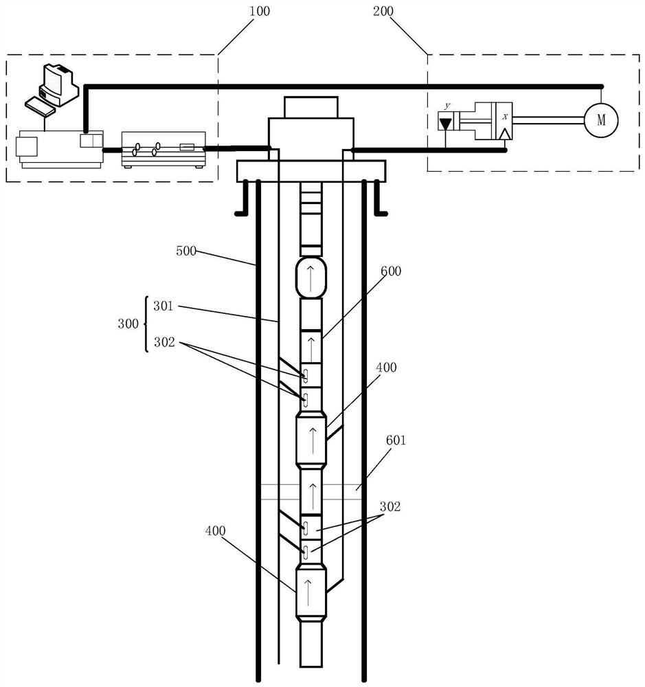
[0055] See figure 1 , the first aspect of the embodiment of the present invention provides an intelligent well completion system based on optical fiber monitoring and layered flow control, including: a surface signal processing subsystem 100, a surface hydraulic subsystem 200, a downhole dynamic monitoring subsystem 300 and a plurality of flow control device 400. The downhole dynamic monitoring subsystem 300 includes a sensing optical fiber 301 and a plurality of optical fiber sensor assemblies 302 . The sensing optical fiber 301 is installed in the oil well casing 500 and extends along the oil well. The sensing optical fiber 301 is located on one side of the oil pipe 600 . The upper end of the sensing optical fiber 301 is connected to the surface signal processing subsystem 100 . In this embodiment, the sensing optical fiber 301 runs through all production layers downhole, and a packer 601 is arranged between two adjacent production layers, and the sensing optical fiber 301 ...

Embodiment 2

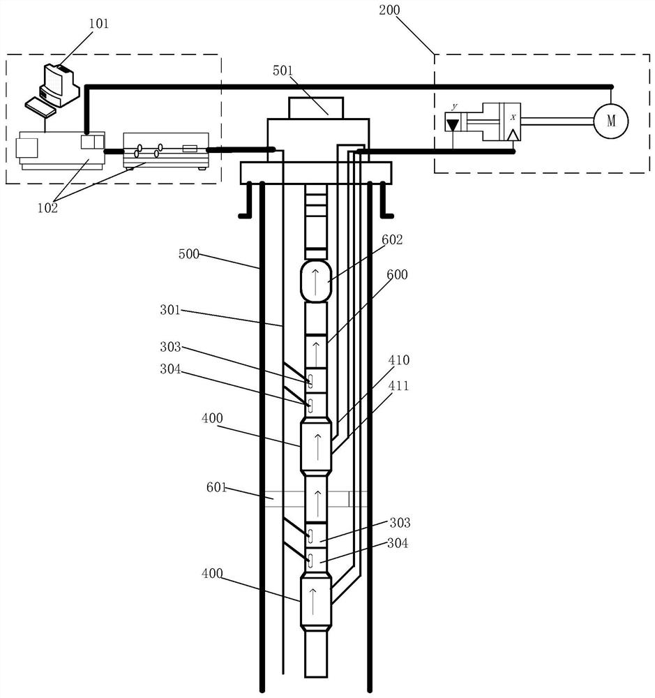
[0063] Such as figure 2 As shown, this embodiment is based on the first embodiment, and further defines that the sensing optical fiber 301 passes through the wellhead Christmas tree 501 and is fixed on one side of the tubing 600 . In this embodiment, the oil well pump 602 is arranged on the oil pipe 600 , and the sensing optical fiber 301 is located on one side of the oil pipe 600 and the oil well pump 602 . Further, the sensing optical fiber 301 can also detect and monitor the working state of the oil well pump 602 . Specifically, the sensing optical fiber 301 can sense vibration and sound waves generated by the oil well pump 602 during operation.

[0064] Further, as figure 2 As shown, the ground signal processing subsystem 100 includes: a server 101 and a signal processor 102 . The server 101 is electrically connected to the signal processor 102 . The signal processor 102 is connected to the sensing optical fiber 301, and the signal processor 102 is electrically conne...

Embodiment 3

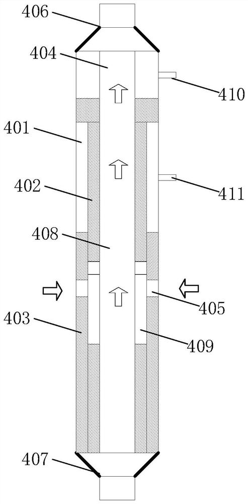
[0074] Such as Figure 2-Figure 4 As shown, the second aspect of the embodiment of the present invention provides an intelligent well completion method based on optical fiber monitoring and layered flow control, which is applied to the monitoring system of the first embodiment above, including the following steps:

[0075] Step 1, the ground signal processing subsystem 100 generates an excitation light source for the sensing fiber 301 .

[0076] Step 2: After receiving the excitation light source, the optical fiber sensor assembly 302 detects the state of the production layer and returns the first optical signal to the ground signal processing subsystem 100, and the sensing optical fiber 301 returns the second optical signal. In this step, the state of the production layer includes temperature, pressure and flow. The sensing fiber 301 uses the incident laser pulse to excite the corresponding backscattering spectrum signals in the sensing fiber 301, that is, Rayleigh, Brilloui...


PUM


Abstract

The invention discloses an intelligent well completion system based on optical fiber monitoring and layered flow control. The intelligent well completion system comprises a ground signal processing subsystem, a ground hydraulic subsystem, an underground dynamic monitoring subsystem and a plurality of flow control devices. The underground dynamic monitoring subsystem comprises a sensing optical fiber and a plurality of optical fiber sensor assemblies; the sensing optical fiber is arranged in an oil well casing in a penetrating mode and extends along an oil well; and the optical fiber sensor assemblies are fixedly arranged on the outer wall of an oil pipe and connected with the sensing optical fiber. The ground signal processing subsystem is electrically connected with the ground hydraulic subsystem through a control cable. The flow control devices are connected with the oil pipe and the ground hydraulic subsystem. The invention further provides an intelligent well completion method based on optical fiber monitoring and layered flow control. Underground distributed monitoring is realized, production halt monitoring is not needed, and the measurement cost is reduced. The detection precision is improved, and the monitoring system and the monitoring method which are high in reliability and high in stability are realized.

Description

technical field [0001] The invention belongs to the field of oil well monitoring systems, and in particular relates to an intelligent well completion system and method based on optical fiber monitoring and layered flow control. Background technique [0002] In the process of exploration and development of oil and gas fields, after the oil and gas wells are conventionally completed, various physical means can be used to measure downhole fluids, pressure and temperature of oil and gas reservoirs, and visualization of downhole oil and gas reservoirs from the surface. Collect, screen, analyze and research to obtain the optimal production plan of oil and gas wells, and further use ground control equipment to remotely install intelligent measurement and control equipment (operating valves or sliding sleeve switches, downhole oil-water separators, etc.) installed in downhole oil and gas layers. In the case of moving pipe strings, according to the conditions of oil wells, water inje...

Claims


Application Information

Patent Timeline
IPC IPC(8): E21B47/135E21B47/06E21B47/07E21B47/00
CPCE21B47/00E21B47/06
Inventor 黄磊周明刚王振华李晓东荣光辉杨红刚杨成刘海
Owner XIAN SITAN INSTR
Why Eureka
Try Eureka