
Optimization model for realizing collaborative production of oil and gas wells on offshore platform

An optimization model and offshore platform technology, applied in design optimization/simulation, wellbore/well components, special data processing applications, etc., can solve problems affecting economic benefits, long-term stable production, production wells cannot be maintained, etc., to achieve flexibility Strong, fast response effect

Pending Publication Date: 2021-07-23
CHINA UNIV OF GEOSCIENCES (BEIJING)
View PDF8 Cites 2 Cited by
  • Summary
  • Abstract
  • Description
  • Claims
  • Application Information

AI Technical Summary

Problems solved by technology

However, high-yield liquid wells are often the wells with the highest oil and gas production, which will reduce the overall productivity of the production platform and affect economic benefits;
[0008] 3. Single well parameter adjustment usually cannot ensure that all well groups on the platform are in the optimal state under the current production conditions, making it impossible for production wells to maintain stable production for a long time

Method used


Image

  • Optimization model for realizing collaborative production of oil and gas wells on offshore platform
  • Optimization model for realizing collaborative production of oil and gas wells on offshore platform
  • Optimization model for realizing collaborative production of oil and gas wells on offshore platform

Examples


Embodiment 1

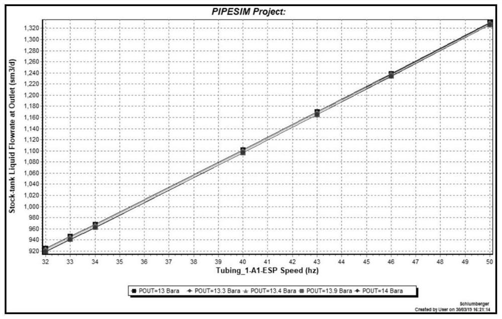
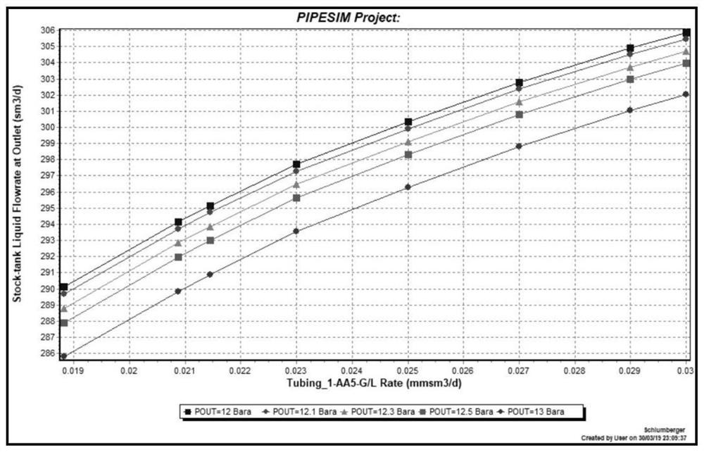
[0103] Assuming that the sewage treatment capacity is reduced to 5500m 3 / d, the total amount of gas injection is 10×10 4 m 3 / d, the gas injection volume of a single well shall not exceed 3×10 4 m 3 / d, the optimal displacement interval of the electric pump well is based on the performance test curve of the electric submersible pump, and the following three schemes are designed, see Table 3 (optimized design scheme 1), table 4 (optimized design scheme 2), and table 5 (optimized design scheme 3):

[0104] table 3

[0105]

[0106] As described in Example 1, the difference is the frequency of the electric pump well and the gas injection rate of the gas lift well.

[0107] Table 4

[0108]

[0109] As described in Example 1, the difference is the frequency of the electric pump well and the gas injection rate of the gas lift well.

[0110] table 5

[0111]

Embodiment 2

[0113] Assume that the upper limit of sewage treatment capacity is 5000m 3 / d, the total amount of gas injection is 8×10 4 m 3 / d, the gas injection volume of a single well shall not exceed 2.5×10 4 m 3 / d, the optimal displacement range of the electric pump well is based on the performance test curve of the electric submersible pump, and the following three schemes are designed, see Table 6 (optimized design scheme 4), table 7 (optimized design scheme 5), and table 8 (optimized design scheme 6):

[0114] Table 6

[0115]

[0116] As described in Example 2, the difference is the frequency of the electric pump well and the gas injection rate of the gas lift well.

[0117] Table 7

[0118]

[0119] As described in Example 2, the difference is the frequency of the electric pump well and the gas injection rate of the gas lift well.

[0120] Table 8

[0121]


PUM


Abstract

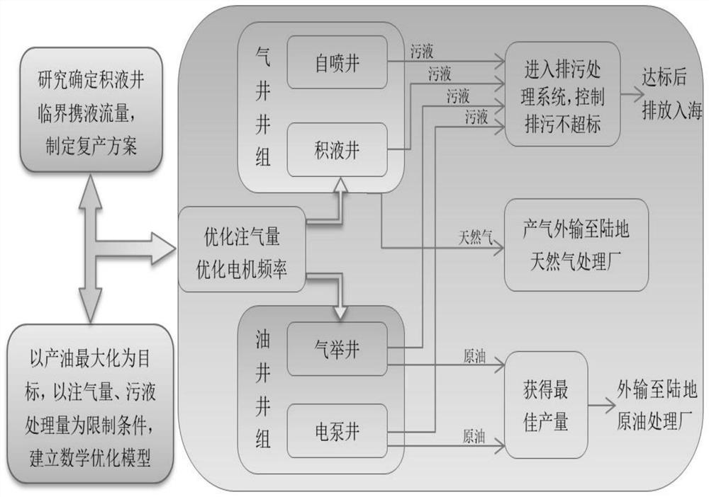
The invention discloses an optimization model for realizing collaborative production of oil and gas wells of an offshore platform. A method in the model comprises the steps that an electric pump well group production characteristic equation and a gas lift well group production characteristic equation are constructed; the parameter ranges of the platform discharge capacity, the electric pump unit frequency and the total gas injection amount are set; and finally an intelligent optimization system of the offshore oil and gas production platform is established. The single well productivity optimization and the full well group productivity maximization of the offshore platform under the production requirement of limited discharge capacity can be effectively realized. According to the method, blindness and low efficiency of single well parameter adjustment are avoided, and the oil and gas well group production scheme making efficiency under complex conditions can be remarkably improved.

Description

technical field [0001] The invention relates to the technical field of oil recovery engineering, more specifically, it relates to an optimization model for realizing coordinated production of oil and gas wells on an offshore platform. Background technique [0002] With the development of onshore oil resources becoming increasingly scarce and oil quality declining, the difficulty of exploitation has increased significantly, and offshore oil resources have gradually received attention. Until recent years, offshore oil exploitation technology and platform construction have gradually matured, and due to the vast ocean area and most of them have not yet been explored and developed, with continuous breakthroughs in drilling and production technology, offshore oil will surely become an important pole of oil exploitation . [0003] Offshore oil exploitation relies on offshore oil production platforms. Compared with onshore oil and gas fields, the development of offshore oil and ga...

Claims


Application Information

Patent Timeline
IPC IPC(8): E21B49/00G06F30/20G06F17/15
CPCE21B49/00G06F30/20G06F17/15
Inventor 范喆刘鹏程
Owner CHINA UNIV OF GEOSCIENCES (BEIJING)
Learn More