Furnace end structure

A furnace head and gas outlet technology, which is applied in the field of furnace head structure, can solve the problems of flame being blown by wind, unstable combustion, low combustion thermal efficiency, etc., and achieve the effects of avoiding continuous leakage, improving combustion support rate, and improving safety.

Pending Publication Date: 2021-07-23
陈祥平
View PDF9 Cites 0 Cited by
  • Summary
  • Abstract
  • Description
  • Claims
  • Application Information

AI Technical Summary

Problems solved by technology

[0002] The existing gas burner has fewer gas outlets entering the gas distributor. During the use of the gas burner, the gas flow is not balanced and stable, resulting in insufficient combustion of the gas, and there is no buffer between the intake pipe and the burner outlet. area, the gas cannot stably enter the combustion area from the gas outlet, resulting in unstable combustion; the thickness of the outer ring and inner ring wall is not enough to form a flame protection ring and a gas guide ring, which may easily cause the flame to be blown by the wind; the air inlet is not set properly Reasonable, the air cannot reach the inner side of the outer ring and inner ring smoothly, resulting in low combustion thermal efficiency; there is no alarm mechanism, and when a gas leak occurs, people cannot cut off the gas supply through the leak signal to avoid accidents

Method used


Image

  • Furnace end structure
  • Furnace end structure
  • Furnace end structure

Examples


Embodiment Construction

[0030] The following will clearly and completely describe the technical solutions in the embodiments of the present invention with reference to the accompanying drawings in the embodiments of the present invention. Obviously, the described embodiments are only some of the embodiments of the present invention, not all of them. Based on the embodiments of the present invention, all other embodiments obtained by persons of ordinary skill in the art without making creative efforts belong to the protection scope of the present invention.

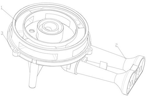
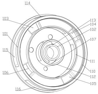
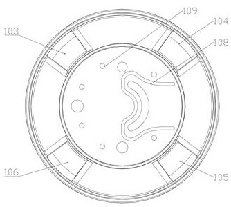
[0031] Please refer to the attached Figure 1-12 , an embodiment provided by the present invention: a furnace head structure, including a mixer 1, a base 3, and an intake pipe group 2, the mixer 1 includes an outer ring 101, an inner ring 102, and the space between the outer ring 101 and the inner ring 102 A first air outlet 103, a second air outlet 104, a third air outlet 105, and a fourth air outlet 106 are provided. The inner side of the inner...


PUM


Abstract

The invention discloses a furnace end structure, and relates to the technical field of gas furnace ends. The furnace end structure comprises a mixer, the mixer comprises an outer ring and an inner ring, a first gas outlet, a second gas outlet, a third gas outlet and a fourth gas outlet are formed between the outer ring and the inner ring, and a fifth gas outlet is formed in the inner side of the inner ring; and the first gas outlet, the second gas outlet, the third gas outlet and the fourth gas outlet are annularly and uniformly distributed between the outer ring and the inner ring, and the first gas outlet, the second gas outlet, the third gas outlet and the fourth gas outlet are the same in shape and are rectangular. The furnace end structure has the advantages that the structure is simple, the outer ring and the inner ring are provided with the ring walls distributed in a concentric circle mode, a flame protection ring and a gas guide ring are formed, flames are prevented from being blown by wind, safety is improved, and gas can be exhausted accurately; and the gas outlets are multiple, so that gas is fully combusted, and the mixer and the base can be quickly disassembled and assembled.

Description

technical field [0001] The invention relates to the technical field of gas burners, in particular to a burner structure. Background technique [0002] The existing gas burner has fewer gas outlets entering the gas distributor. During the use of the gas burner, the gas flow is not balanced and stable, resulting in insufficient combustion of the gas, and there is no buffer between the intake pipe and the burner outlet. area, the gas cannot stably enter the combustion area from the gas outlet, resulting in unstable combustion; the thickness of the outer ring and inner ring wall is not enough to form a flame protection ring and a gas guide ring, which may easily cause the flame to be blown by the wind; the air inlet is not set properly Reasonable, the air cannot reach the inner side of the outer ring and the inner ring smoothly, resulting in low combustion thermal efficiency; there is no alarm mechanism, and when a gas leak occurs, people cannot cut off the gas supply through th...

Claims


Application Information

Patent Timeline
Patent Type & Authority Applications(China)
IPC IPC(8): F23D14/02F23D14/46
CPCF23D14/02F23D14/46
Inventor 陈祥平
Owner 陈祥平
Why Eureka
Try Eureka