RCS measurement system and method

A measurement system and azimuth angle technology, applied in radio wave measurement systems, instruments, etc., to achieve the effects of a wide measurement range, a large measurement field of view, and a large measurement angle

Pending Publication Date: 2021-07-23
佛山蓝谱达科技有限公司
View PDF0 Cites 5 Cited by
  • Summary
  • Abstract
  • Description
  • Claims
  • Application Information

AI Technical Summary

Problems solved by technology

[0005] The main purpose of the present invention is to propose a RCS measurement system and method, aiming at solving the existing technical problems

Method used


Image

  • RCS measurement system and method
  • RCS measurement system and method
  • RCS measurement system and method

Examples


Embodiment 1

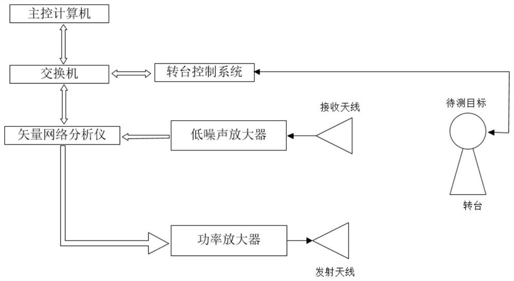
[0036] figure 1 It is a structural schematic diagram of an embodiment of the RCS measurement system of the present invention. Such as figure 1 As shown, an RCS measurement system includes: a vector network analyzer connected electrically, a transceiver antenna, a control machine, a power amplifier, and a turntable control system;

[0037] Vector network analyzer is used for sending and receiving radio frequency signals;

[0038] The control machine realizes the control of the vector network analyzer through the LAN bus, connects the control machine and the vector network analyzer with a network cable, and sets the IP (Internet Protocol, the protocol for interconnection between networks) address of the vector network analyzer and the IP address of the control machine Same, realize data communication through SCPI (Standard Commands for Programmable Instruments, abbreviation: SCPI) control command;

[0039] The transceiver antenna is provided with a receiving antenna and a tra...

Embodiment 2

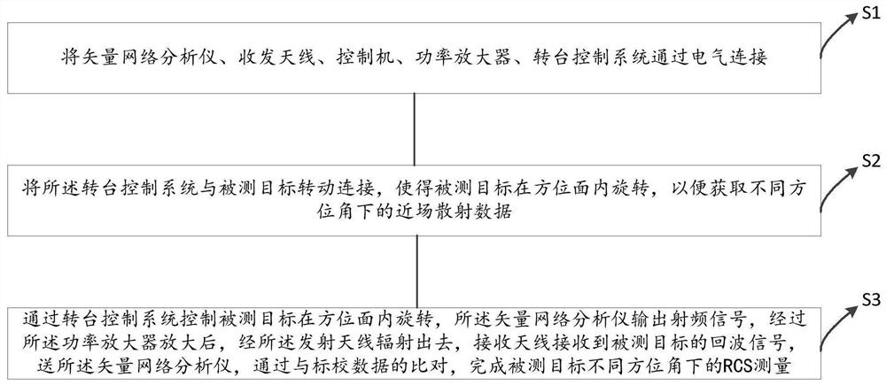
[0052] image 3 It is a flowchart of the RCS measurement method of the present invention. Such as image 3 Shown, a kind of RCS measurement method at least comprises the steps:

[0053] S1. Electrically connect the vector network analyzer, transceiver antenna, controller, power amplifier, and turntable control system;

[0054] S2. Connect the turntable control system to the target to be measured so that the target to be measured rotates in the azimuth plane, so as to obtain near-field scattering data at different azimuths;

[0055] S3. Control the target to be measured to rotate in the azimuth plane through the control system of the turntable. The vector network analyzer outputs the radio frequency signal. After being amplified by the power amplifier, it is radiated through the transmitting antenna. The network analyzer, through comparison with the calibration data, completes the RCS measurement of the target under different azimuth angles.

[0056] When measuring the targ...


PUM


Abstract

The invention discloses an RCS measurement system and method. The system comprises a vector network analyzer, a transceiving antenna, a control machine, a power amplifier and a rotary table control system which are electrically connected. The vector network analyzer is used for transmitting and receiving radio frequency signals; the control machine controls the vector network analyzer through an LAN (Local Area Network) bus; the turntable control system is used for controlling a to-be-measured target to rotate in an azimuth plane so as to acquire near-field scattering data under different azimuth angles; and a to-be-measured target is controlled by the turntable control system to rotate in an azimuth plane, the vector network analyzer outputs a radio frequency signal, the radio frequency signal is amplified by the power amplifier and then radiated by the transmitting antenna, the receiving antenna receives an echo signal of the to-be-measured target, the echo signal is sent to the vector network analyzer and compared with calibration data, and RCS measurement of the to-be-measured target under different azimuth angles is completed. The measurement range is wide, the measurement field of view is large, the RCS scattering matrix and target broadband multi-dimensional imaging characteristics can be measured, and electromagnetic scattering characteristic data can be visually obtained.

Description

technical field [0001] The invention relates to the technical field of microwave measurement, in particular to an RCS measurement system and method. Background technique [0002] With the rapid development of electronic modern electronic technology, the work faced by microwave measurement is becoming more and more complex. Among them, the measurement of target radar cross-section RadarCross-Section (RCS) is an important step in the field of microwave measurement. The radar cross-section of the target is a hypothetical area. By describing the amplitude of the wave reflected back to the radar when the target is illuminated by the radar, it is used to analyze the electromagnetic characteristics of the target. The measurement of the radar cross-section of the target can not only obtain the basic information of the target The understanding of scattering phenomena can test the results of theoretical analysis, and a large amount of target feature data can be obtained to establish a...

Claims


Application Information

Patent Timeline
Patent Type & Authority Applications(China)
IPC IPC(8): G01S7/40
CPCG01S7/40
Inventor 梁家军黄冠龙
Owner 佛山蓝谱达科技有限公司
Why Eureka
Try Eureka