
Electromagnetic scattering simulation method for electrically large-size target under near-field condition

An electrically large size, electromagnetic scattering technology, applied in design optimization/simulation, radio wave measurement systems, special data processing applications, etc., can solve problems such as high memory consumption, low computing efficiency, failure, etc., to achieve high simulation accuracy and fast calculation. The effect of high efficiency, high distortion-free characteristics

Active Publication Date: 2021-07-23
UNIV OF ELECTRONIC SCI & TECH OF CHINA
View PDF11 Cites 2 Cited by
  • Summary
  • Abstract
  • Description
  • Claims
  • Application Information

AI Technical Summary

Problems solved by technology

However, the antenna pattern is only applicable to the situation where the antenna is located in the far-field condition. When the distance between the antenna and the target does not meet the far-field condition of the antenna, this method will fail
[0008] At the same time, in the prior art, commercial software Feko is also used to simulate with the method of moments. Although this method can achieve the required calculation accuracy, it also has the disadvantages of large memory consumption and low calculation efficiency.

Method used


Image

  • Electromagnetic scattering simulation method for electrically large-size target under near-field condition
  • Electromagnetic scattering simulation method for electrically large-size target under near-field condition
  • Electromagnetic scattering simulation method for electrically large-size target under near-field condition

Examples


Embodiment 1

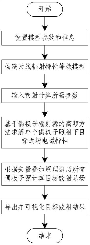
[0096] Such as Figure 1-Figure 3 Shown:

[0097] An electromagnetic scattering simulation method for an electrically large-sized target under near-field conditions includes the following steps:

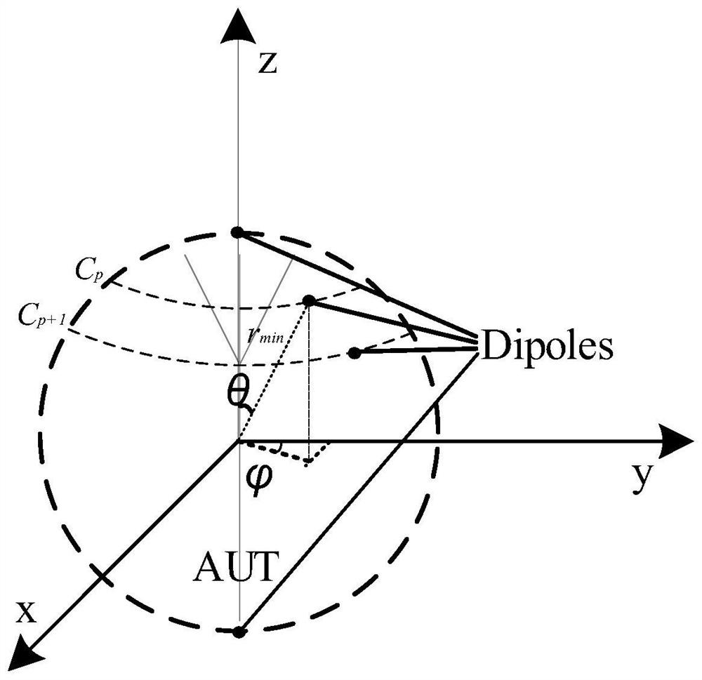
[0098] S1. Constructing an equivalent model of antenna radiation characteristics composed of dipole arrays according to the radar antenna parameters corresponding to the real target radar scene;

[0099] S2, setting the physical parameters and position parameters of the target platform and the physical parameters and position parameters of the observation area, so that the target platform and the radar antenna are in a near-field state;

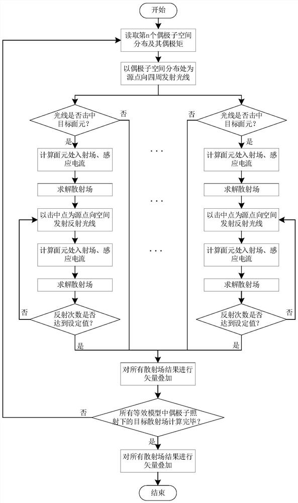
[0100] S3, regard the dipole source in the dipole array as a radiation source, and then calculate the total electromagnetic scattering field of the target platform under the irradiation of the radiation source under the scattering condition parameters by using a high-frequency method;

[0101] S4. Visualize the total electromagnetic scattering fie...

Embodiment 2

[0155] Such as Figure 4 Shown:

[0156] The radar antenna is a horn antenna;

[0157] The size parameter of the radar antenna is: 55mm×42.8mm×76.2mm; the operating frequency f of the radar antenna is 8GHz, and the wavelength of the radar antenna is λ.

[0158] Preferably, the target platform is a flat structure or a large surface ship;

[0159] The physical parameters of the target platform are: 10λ×10λ, and the position parameters of the target platform are: 30λ away from the radar antenna;

[0160] Preferably, the location parameter of the observation area is: a square area with a size of 10λλ×10λλ at 20λ above the radar antenna; λ is the wavelength of the radar antenna.

[0161] The above parameters can make it in a near-field state.

[0162] After the above parameters are substituted into the method of the above-mentioned embodiment 1, an equivalent model is constructed such as Figure 5 shown.

[0163] Then in the above-mentioned embodiment 1, the number of ray bou...


PUM


Abstract

The invention discloses an electromagnetic scattering simulation method for an electrically large-size target under a near-field condition. The method comprises the following steps: S1, constructing an antenna radiation characteristic equivalent model composed of a dipole array according to radar antenna parameters corresponding to a real target radar scene; s2, setting a physical parameter and a position parameter of the target platform and a physical parameter and a position parameter of the observation region, so that the target platform and the radar antenna are in a near-field state; s3, taking a dipole source in the dipole array as a radiation source, and calculating an electromagnetic scattering total field of the target platform under radiation of the radiation source by adopting a high-frequency method under scattering condition parameters; and S4, carrying out visualization processing on the electromagnetic scattering total field. The method has very high simulation precision and undistorted characteristics, and also has very low memory calculation loss and fast calculation efficiency.

Description

technical field [0001] The invention relates to an electromagnetic scattering simulation method, in particular to an electromagnetic scattering simulation method for an electrically large-sized target under near-field conditions. Background technique [0002] In practical engineering applications, usually according to the far-field condition criterion (where r is the observation distance from the radar to the target, D is the size of the target, and λ is the wavelength of the radar wave). The radar antenna field is divided into two parts, the near field and the far field. Most of the existing research on target electromagnetic scattering focuses on the far-field region. The electromagnetic scattering characteristics in this region are only related to the geometric shape of the target, the electromagnetic properties of the material, and the frequency, angle, and polarization of the incident wave, and have nothing to do with the radar antenna itself. Therefore, it can be base...

Claims


Application Information

Patent Timeline
IPC IPC(8): G06F30/20G01S7/02
CPCG06F30/20G01S7/02
Inventor 杨伟周礼来方磊雷世文何子远田径胡皓全陈波
Owner UNIV OF ELECTRONIC SCI & TECH OF CHINA
Learn More