Supercharge Your Innovation With Domain-Expert AI Agents!

Near-field sparse array design method

A design method and sparse array technology, applied in the field of array antenna design, can solve the problems of affecting the corresponding beam effect of the array, high time complexity, insufficient coverage, etc., and achieve the effect of flexible sparse array design and expansion of search space.

Active Publication Date: 2021-07-23
UNIV OF ELECTRONICS SCI & TECH OF CHINA +1
View PDF9 Cites 0 Cited by
  • Summary
  • Abstract
  • Description
  • Claims
  • Application Information

AI Technical Summary

Problems solved by technology

Compared with the genetic algorithm, the search space of this algorithm is large enough, but because the entire solution space needs to be traversed in each search, its time complexity is high, which is not good for systems with strong real-time performance, especially for the number of array elements. When the array is larger, its adjustment to the array is lagging
[0005] Although the above-mentioned sparse array design methods can solve the problem of downsizing the array in near-field beamforming to a certain extent, the two types of methods have some deficiencies, and it is difficult to achieve a good balance in terms of performance and time complexity.
When high beam performance is required in the array design, in order to ensure a sufficiently large search space, the corresponding algorithm often has a large time complexity; in order to run in a real-time system, a solution with a low time complexity needs to be adopted. At this time, the algorithm Insufficient coverage of the search space may lead to performance degradation and affect the final beam effect of the array

Method used


Image

  • Near-field sparse array design method
  • Near-field sparse array design method
  • Near-field sparse array design method

Examples


Embodiment 1

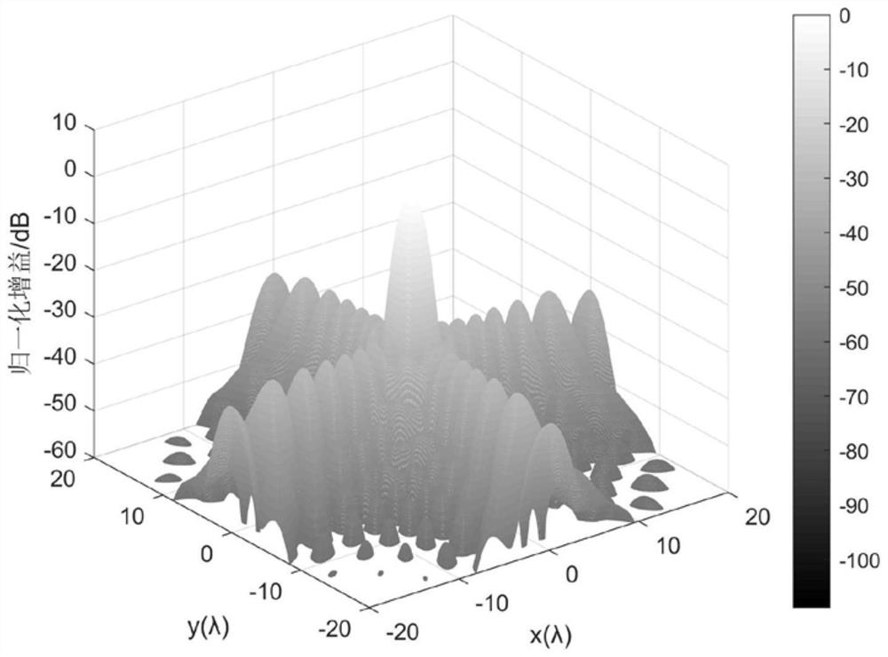
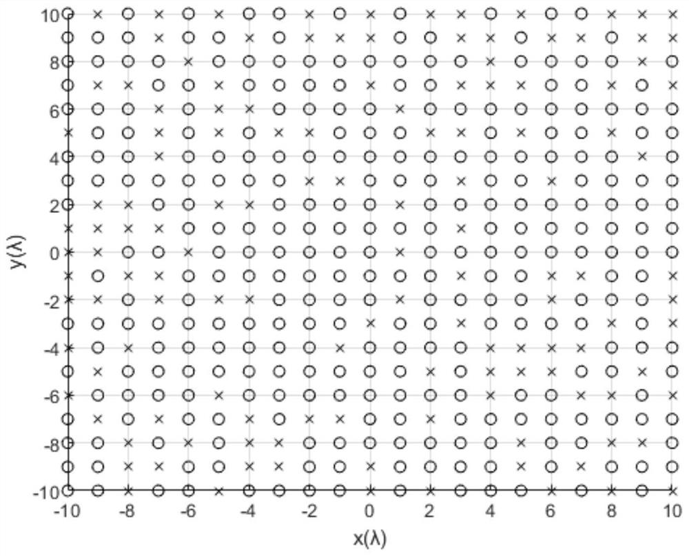
[0038]The purpose of this embodiment is to verify that the algorithm proposed by the present invention can perform sparse array design, and that the beam pattern corresponding to the array still has certain performance after sparse. In this embodiment, the size of the array is 21 × 21 array elements, a total of 441 array elements, and a two-dimensional planar array with an interval of half a wavelength is carried out. The array element at the physical center of the array is used as the reference array element and set as the origin of the coordinate system . The focus point is located at coordinates (0,0,15λ), and the maximum sidelobe gain of the beam pattern corresponding to the initial weight vector does not exceed -30dB. Perform 70% sparse array design and delete 132 array elements.

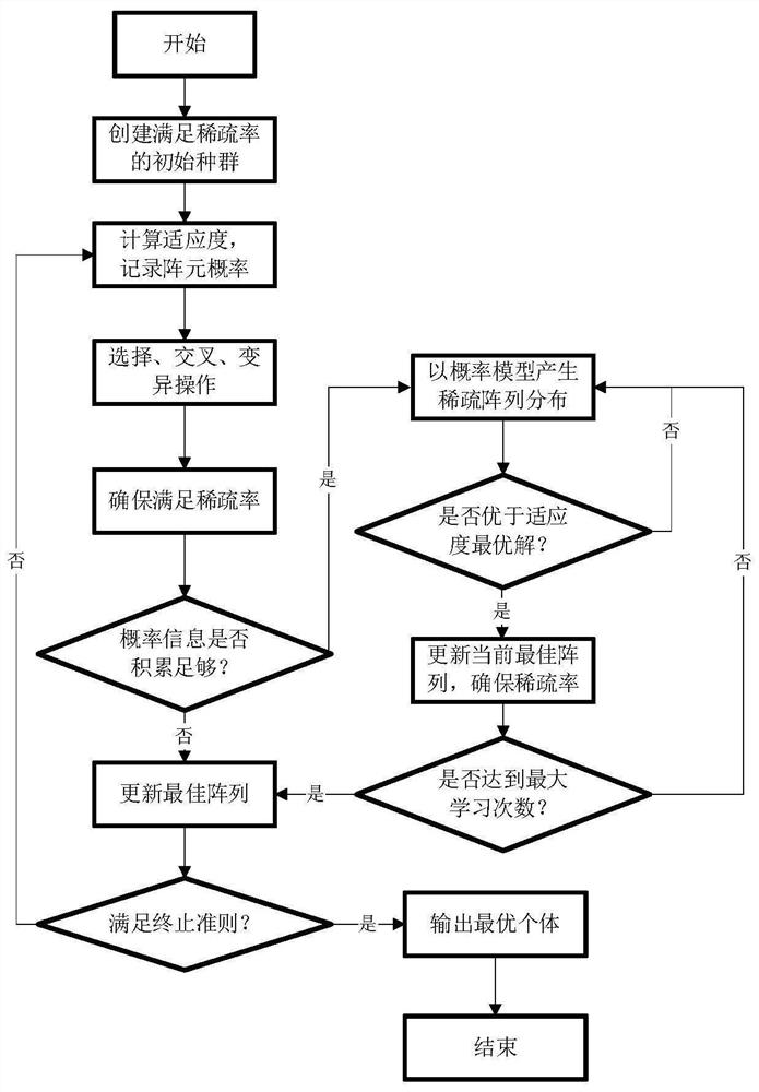
[0039] The beamforming simulation implementation method of this embodiment is shown in the attached figure 1 shown. attached figure 2 The beam pattern corresponding to the basic model in t...

Embodiment 2

[0041] The purpose of this embodiment is to show that the algorithm proposed by the present invention can achieve a better sparse effect for small arrays with non-standard spacing. In this embodiment, the size of the array is 5×5 array elements, with a total of 25 array elements, and a two-dimensional planar array with an interval of 0.7 times the wavelength is carried out. The array element at the physical center of the array is used as the reference array element, and is set as the coordinate system origin. The focus point is located at coordinates (0,0,3λ), and the maximum sidelobe gain of the beam pattern corresponding to the initial weight vector does not exceed -25dB. Perform a 70% sparse array and delete 8 array elements.

[0042] attached Figure 5 The beam pattern corresponding to the basic model in this embodiment is given, and the model is a low sidelobe focused beam model. Consistent with Example 1, the number of iterations of the genetic algorithm is 200, the c...


PUM


Abstract

The invention belongs to the technical field of array antenna design, and relates to a near-field sparse array design method. The method comprises the following steps: firstly, according to a given initial uniform array, calculating a weight vector capable of realizing a near-field focusing beam, and taking the weight vector as a basis of a sparse array; and in the calculation process, firstly adopting a traditional genetic algorithm to carry out array design, after the genetic algorithm is carried out for a certain number of times, performing probability learning algorithm iteration before each turn of genetic algorithm is finished, and if a solution with higher fitness is generated within a certain number of learning times, replacing the optimal solution in the current genetic algorithm with the solution and is reserved. Compared with a traditional genetic algorithm and a greedy search algorithm, the method has the advantages that time complexity and design performance are well considered, and the method has certain flexibility. According to the method, high-performance global search can be carried out on a small array in actual engineering, and a better feasible solution is found.

Description

technical field [0001] The invention belongs to the technical field of array antenna design and relates to a near-field sparse array design method. Background technique [0002] With the development of array antenna technology, the near-field antenna array has become a hot topic under the background of the mature research of far-field antenna array. Near-field antenna arrays have been widely used in microphone arrays, wireless charging technology, radio frequency identification technology, sonar, radar and other fields, involving civilian, commercial and even military scenarios. In many studies, a uniform array with a half-wavelength element spacing is usually used as the basic model for research, and the array at this time is called a standard array. In the standard array, the beam pattern of the array has a better focusing effect, and because there are more elements in the array, the control of the energy is more flexible. In order to reduce resource overhead, some eleme...

Claims


Application Information

Patent Timeline
Patent Type & Authority Applications(China)
IPC IPC(8): G06F30/27G06N3/12G06F111/06
CPCG06F30/27G06N3/126G06F2111/06
Inventor 甘露潘延徐政五廖红舒
Owner UNIV OF ELECTRONICS SCI & TECH OF CHINA
Features
  • R&D
  • Intellectual Property
  • Life Sciences
  • Materials
  • Tech Scout
  • Unparalleled Data Quality
  • Higher Quality Content
  • 60% Fewer Hallucinations
Learn More