Insulating collector plate and fuel cell

A fuel cell and collector plate technology, applied to fuel cells, fuel cell parts, circuits, etc., can solve problems affecting the performance and service life of the stack, poor sealing and insulation effects, and inability to achieve insulation, etc., to achieve overall Strong performance, reduced contact resistance, and reduced R&D costs

Pending Publication Date: 2021-07-23
上海氢晨新能源科技有限公司
View PDF0 Cites 3 Cited by
  • Summary
  • Abstract
  • Description
  • Claims
  • Application Information

AI Technical Summary

Problems solved by technology

However, what the existing collector plate adopts is the form of a whole piece of metal plate, and its size is also the same as the size of the cross-sectional area in the core, which is prone to the following problems: the sealing and insulating effect of the form of the whole piece of metal plate is poor, Especially in the public pipe part where the collector plate is in contact w

Method used


Image

  • Insulating collector plate and fuel cell
  • Insulating collector plate and fuel cell

Examples


Embodiment 1

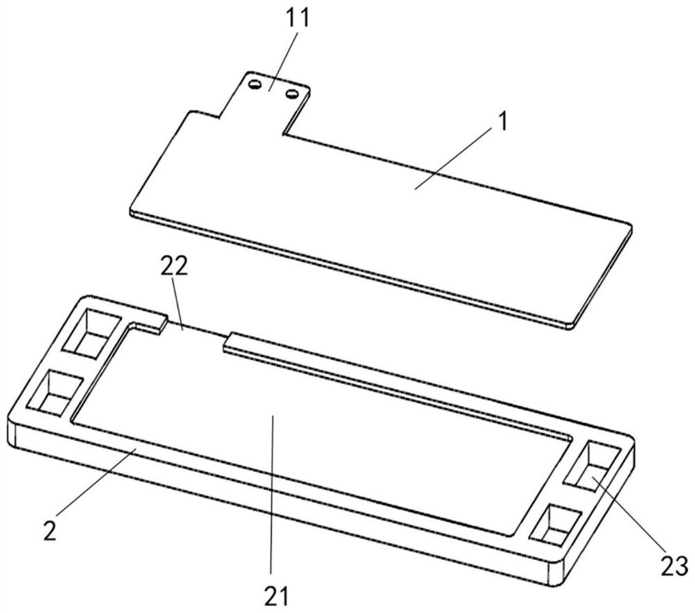
[0024] like figure 1 As shown, this embodiment provides an insulating current collector, including a board core module 1 and an insulating board module 2 . A groove structure 21 is provided in the center of the insulating board module 2 , and an opening groove 22 is provided on the upper edge of the insulating board module. One end of the opening groove 22 is connected to the groove structure 21 , and the other end extends to the edge of the insulating board module 2 . . The shape of the board core module 1 matches the shape of the groove structure 21 ; a lead-out end 11 is provided on one side of the board core module 1 . The board core module 1 is embedded in the groove structure 21 , the lead end 11 is embedded in the opening, and the length of the lead end 11 is greater than the length of the opening slot 22 , so that the end of the lead end 11 is suspended outside the insulating board module 2 .

[0025] In this embodiment, the thickness of the board-core module 1 is co...

Embodiment 2

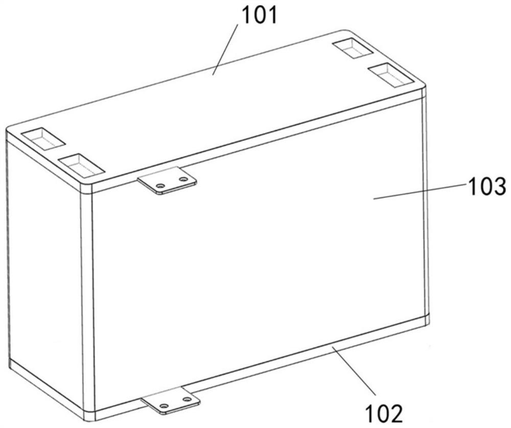
[0030] like figure 2 As shown, this embodiment provides a fuel cell including a casing (not shown in the figure), an insulating current collector plate and a core 103 . The insulating current collector plate in this embodiment is divided into an upper end current collector plate 101 and a lower end current collector plate 102 . The structure of the core is the same as that of the existing fuel cell core 103, so it is no longer unfolded. The structure of the upper current collecting plate 101 is the same as that of the insulating current collecting plate in the first embodiment. The structure of the lower-end current collecting plate 102 is similar to the structure of the insulating current collecting plate in the first embodiment, and the difference lies in that the two ends of the insulating plate module 2 are not provided with the through-hole structures 23 . The core 103 with insulating current collector plates at both ends is integrally installed in the casing. The fue...


PUM


Abstract

The invention relates to an insulating collector plate and a fuel cell. The insulating collector plate comprises a plate core module and an insulating plate module, the center of the insulating plate module is provided with a groove structure, the shape of the plate core module is matched with the shape of the groove structure, the plate core module is embedded in the groove structure, the insulating module is provided with an open slot, one end of the open slot is connected with the groove structure, the other end of the open slot is connected with the edge of the insulating plate module, a leading-out end is arranged on the plate core module, after the plate core module is embedded into the groove structure, the leading-out end is embedded into the open slot, and the end part of the leading-out end is suspended outside the insulating plate module. Compared with the prior art, the collector plate has the advantages that the sealing property and the insulating property of the collector plate can be improved, so that a reaction substance does not contact with the plate core module in the working process of the battery, and a complete insulating effect is achieved.

Description

technical field [0001] The present invention relates to the technical field of fuel cells, in particular to an insulating current collector plate and a fuel cell. Background technique [0002] The proton exchange membrane fuel cell is a kind of electrochemical process in which the anode hydrogen is decomposed into protons and electrons through a catalyst, the protons reach the cathode through the proton exchange membrane, and the electrons reach the cathode through an external circuit. The device has the advantages of high efficiency, low temperature, cleanliness and environmental protection. [0003] In the proton exchange membrane fuel cell, the current collector plates are arranged at the upper and lower ends of the core to realize the positive and negative output of the current. However, the existing collector plate is in the form of a whole piece of metal plate, and its size is also the same as the cross-sectional area in the core, which is prone to the following probl...

Claims


Application Information

Patent Timeline
IPC IPC(8): H01M8/0286H01M8/0273H01M8/0276H01M8/0202H01M8/2465
CPCH01M8/0202H01M8/0273H01M8/0276H01M8/0286H01M8/2465Y02E60/50
Inventor 程敬德赵树钊梁鹏麦建明唐厚闻李红涛
Owner 上海氢晨新能源科技有限公司
Why Eureka
Try Eureka