Electric power safety system capable of autonomously switching standby circuit and switching method of electric power safety system

A technology of autonomous switching and power safety, which is applied in the direction of power network operating system integration, circuit devices, and emergency protection circuit devices for limiting overcurrent/overvoltage, and can solve problems such as line overload, increased circuit pressure, and large losses , to avoid arcing and increase safety

Inactive Publication Date: 2021-07-23
田洪昌
View PDF0 Cites 0 Cited by
  • Summary
  • Abstract
  • Description
  • Claims
  • Application Information

AI Technical Summary

Problems solved by technology

[0003] The existing switching method is mainly to use the standby power supply to work and supply power when the common power supply fails. This requires the operator to switch and adjust the circuit. Since the power failure is not predictable, when there is a power failure, after the power failure in the power consumption area, It takes a long time to restore the power, and the arc and filtering caused by contact during the process of the bird ring will also increase the pressure on the circuit, which is prone to the problem of line overload, such as the long-term power failure of some production-oriented enterprises. Under such circumstances, the slurry inside the equipment is formed, causing huge losses. Therefore, a device for fast and autonomous switching circuits is proposed, which can quickly switch between the normal power supply and the backup power supply.

Method used


Image

  • Electric power safety system capable of autonomously switching standby circuit and switching method of electric power safety system
  • Electric power safety system capable of autonomously switching standby circuit and switching method of electric power safety system
  • Electric power safety system capable of autonomously switching standby circuit and switching method of electric power safety system

Examples


Embodiment Construction

[0032] The following will clearly and completely describe the technical solutions in the embodiments of the present invention with reference to the accompanying drawings in the embodiments of the present invention. Obviously, the described embodiments are only some, not all, embodiments of the present invention. Based on the embodiments of the present invention, all other embodiments obtained by persons of ordinary skill in the art without making creative efforts belong to the protection scope of the present invention.

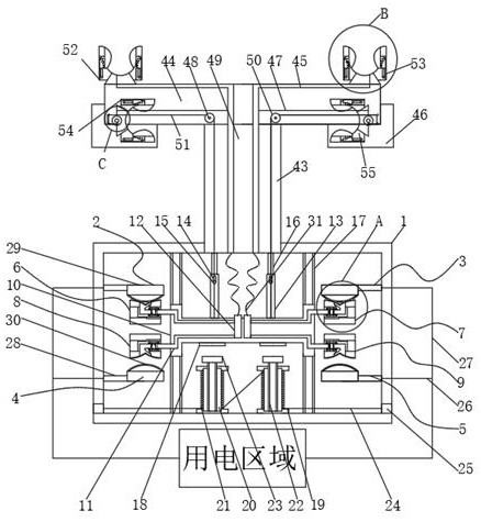
[0033] Such as Figure 1-4 As shown, the present invention provides a technical solution: a power safety system for autonomous switching of standby circuits, including a box body 1, and the top of the left and right sides of the inner wall of the box body 1 are respectively fixedly connected with a common positive electrode contact 2 and a common negative electrode Contact 3, the bottom of the left and right sides of the inner wall of the box body 1 are respec...


PUM


Abstract

The invention relates to the technical field of electric power equipment, and discloses an electric power safety system capable of autonomously switching a standby circuit and a switching method thereof. The system comprises a box body, wherein a common positive electrode contact and a common negative electrode contact are fixedly connected to the upper portions of the left side and the right side of the inner wall of the box body respectively. According to the invention, when the temperature of a common positive electrode contact head, a common negative electrode contact head, a standby positive electrode contact head and a standby negative electrode contact head is too high, a memory metal is subjected to high temperature on a connecting block and a contact block circuit, the memory metal deforms instantly and pulls two bridge frames to move towards the opposite directions, the bridge frame of the connecting block and the contact block is separated from an arc-shaped contact head, andat the moment, a circuit is in a power-off state; when the temperature is normal, under the action of two tension springs, the two bridge frames slowly approach each other, and the circuit is connected again, so that the safety of the switching device can be ensured, the problem of fire caused by faults is avoided, and the safety of the common circuit and the standby circuit is ensured.

Description

technical field [0001] The invention relates to the technical field of electric power equipment, in particular to an electric power safety system and a switching method for autonomous switching of standby circuits. Background technique [0002] Switching between the backup power supply and the normal power supply is to connect the coil of the relay to the mains, connect the normally open contacts of the relay in series in the main circuit, and connect the backup power to the normally closed contacts of the relay. When the mains has voltage, the relay will pull in , the normally open contact is closed, and the system is powered by mains power. When the power fails, the relay coil loses power, the relay resets, the normally closed contact is closed, and the backup power supplies power to the power system through the normally closed contact. [0003] The existing switching method is mainly to use the standby power supply to work and supply power when the common power supply fai...

Claims


Application Information

Patent Timeline
Patent Type & Authority Applications(China)
IPC IPC(8): H02J9/06H02B1/46H02B1/14H02H9/08H01H71/10H01H71/14
CPCH01H71/10H01H71/14H02B1/14H02B1/46H02H9/08H02J9/062Y02B70/30Y04S20/20
Inventor 田洪昌
Owner 田洪昌
Why Eureka
Try Eureka