Vibrating chemical fertilizer producing and screening device for corn cultivation
A technology of screening device and vibration device, which is applied in the fields of filter screen, chemical instrument and method, solid separation, etc., can solve the problem that the screening device cannot adjust the degree of automation, and achieve the effect of preventing clogging and wide practicability.
- Summary
- Abstract
- Description
- Claims
- Application Information
AI Technical Summary
Problems solved by technology
Method used
Image
Examples
Embodiment 1
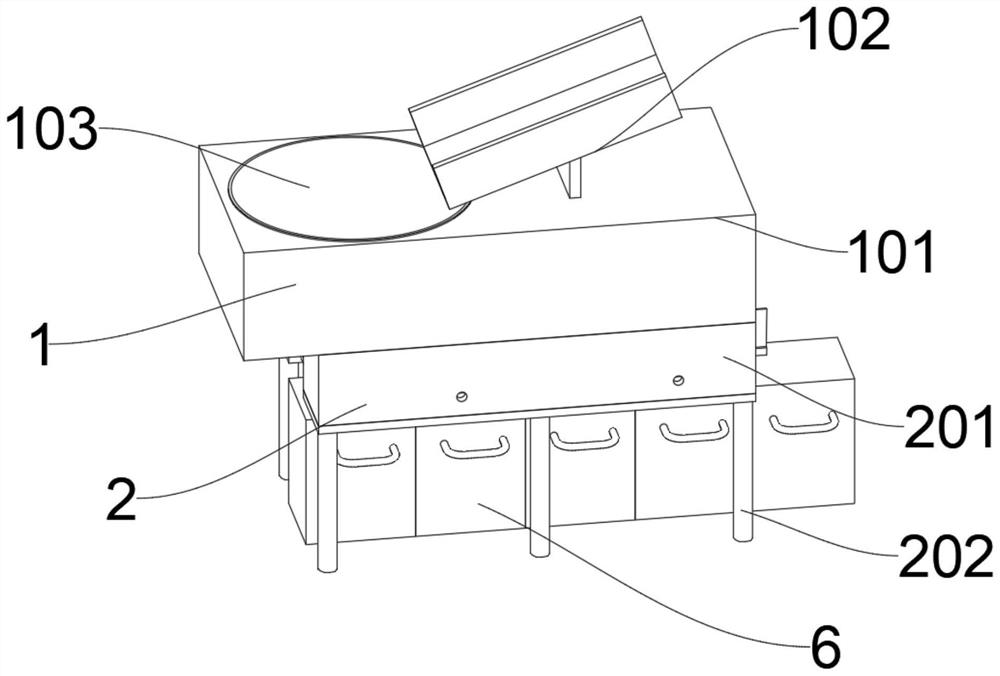
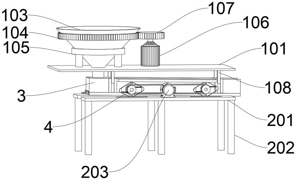
[0032] Please refer to Figure 1-2, a vibrating chemical fertilizer production and screening device for corn cultivation, including a feeding device 1, a vibrating device 2 is installed at the bottom of the feeding device 1, and a sieving device 3 is installed below the feeding device 1. The device 2 includes a protective shell 201, two protective shells 201 are provided, the tops of the two protective shells 201 are respectively connected to the bottoms on both sides of the feeding device 1, the screening device 3 is located between the two protective shells 201, and the vibrating device 2 also Including a vibrator 4, the vibrator 4 is located outside the screening device 3, and a plurality of storage frames 6 are placed below the screening device 3.
[0033] The unloading device 1 comprises a shell 101, the top inner wall of the shell 101 is penetrated with a hopper 103 installed, the top of the shell 101 is welded with a hopper 102, and the bottom of the chute 102 is located ...
Embodiment 2
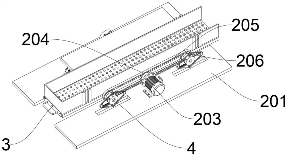
[0036] Please refer to Figures 3-5, the difference in the basis of Embodiment 1 is that the bottom of the protective case 201 is welded with a plurality of support rods 202, and the inner wall of the bottom of the protective case 201 is threaded with a vibration motor 203, and the vibration motor 203 The output end of the drive gear 204 is fixedly connected with the drive gear 204, the bottom inner wall of the protective shell 201 is fixedly connected with the connecting bearing 207, the connecting bearing 207 is located on both sides of the vibrating motor 203, the inner side of the connecting bearing 207 is inserted with a rotating shaft 208, and the rear of the rotating shaft 208 The end is fixedly connected with a driven gear 206, the outer side of the driven gear 206 is meshed with a chain 205, and the inner side of the chain 205 is meshed with the driving gear 204, and the front end of the rotating shaft 208 is fixedly connected with a vibrator 4.
[0037] The screening d...
Embodiment 3
[0040] Please refer to Figures 6-7, the difference between Embodiments 1 and 2 is that the vibrator 4 includes a vibrating plate 401, an adjusting gear 402 is installed inside the vibrating plate 401, and a moving groove is provided inside the vibrating plate 401 403, two moving slots 403 are provided, and the two moving slots 403 are respectively located above and below the adjusting gear 402, the inside of the adjusting gear 402 is fitted with a moving rack 404, and the outer side of the moving rack 404 is fixedly connected with a large circle Arc 405, the moving rack 404 meshes with the adjustment gear 402, the top and bottom of the vibration plate 401 are respectively connected with a spring telescopic rod 406, and the end of the spring telescopic rod 406 is connected with a small arc 407, and the vibrator 4 also includes a belt 408, the belt 408 is sleeved on the outside of the large arc 405 and the small arc 407 .
[0041] The vibrator 4 also includes a control device 5,...
PUM
 Abstract
Description
Claims
Application Information
 - R&D
- Intellectual Property
- Life Sciences
- Materials
- Tech Scout
- Unparalleled Data Quality
- Higher Quality Content
- 60% Fewer Hallucinations
Browse by: Latest US Patents, China's latest patents, Technical Efficacy Thesaurus, Application Domain, Technology Topic, Popular Technical Reports.
© 2025 PatSnap. All rights reserved.Legal|Privacy policy|Modern Slavery Act Transparency Statement|Sitemap|About US| Contact US: help@patsnap.com


