
Special-shaped rivet-free riveting structure and forming device and method

A technology of rivetless riveting and forming device, applied in the field of forming device and special-shaped rivetless riveting structure, can solve the problems of reducing riveting processing efficiency, distance process limitation, etc., and achieves high production efficiency, widening process range and high connection strength Effect

Active Publication Date: 2021-07-27
SHANDONG UNIV
View PDF9 Cites 0 Cited by
  • Summary
  • Abstract
  • Description
  • Claims
  • Application Information

AI Technical Summary

Problems solved by technology

[0006] However, the multi-point riveting method will inevitably reduce the riveting processing efficiency, and the distance between each riveting point is also strictly limited by the process

Method used


Image

  • Special-shaped rivet-free riveting structure and forming device and method
  • Special-shaped rivet-free riveting structure and forming device and method
  • Special-shaped rivet-free riveting structure and forming device and method

Examples


Embodiment 1

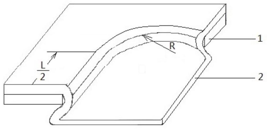
[0059] In a typical implementation of the present invention, 1 / 4 of its structure is as figure 1 As shown, a special-shaped rivetless riveting structure includes a riveted first plate and at least one layer of second plate, the first plate has a special-shaped hole, the second plate is provided with a recess, and the non-recessed part of the second plate is overlapped with the first plate above, the recess protrudes from the shaped hole of the first plate, and the depth of the recess is greater than the sum of the thicknesses of the first plate and the second plate.

[0060] In this implementation, a layer of the second plate is taken as an example for description.

[0061] Wherein, the concave portion includes a bottom surface, and a side wall is provided on the circumferential side of the bottom surface, and the concave portion is formed by the bottom surface and the side wall. The centrally protruding arc shape makes the recess form an undercut structure with a small mouth...

Embodiment 2

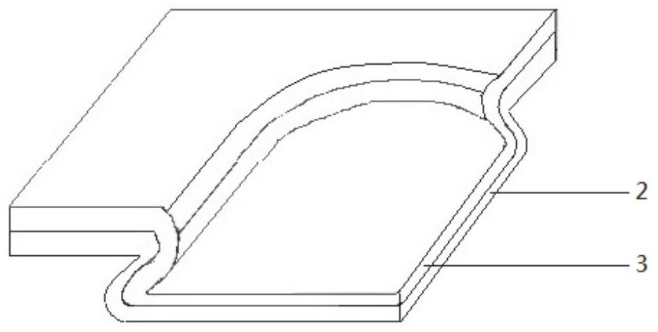
[0079] A special-shaped rivetless riveting structure, 1 / 4 of which is as figure 2 As shown, there are at least two layers of riveted plates, and the multi-layer plates are riveted through recesses, and the shape of the recesses is a special shape.

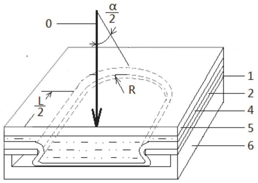
[0080] In this embodiment, the concave portion is in the shape of a key, and the two ends of the concave portion are arc-shaped, which can be a semicircle with a radius of R, the two sides of the concave portion are straight lines, the length of the straight line of the concave portion is L, and the total length of the concave portion is L. +2R, and the length L / width 2R>1 of the straight line.

[0081] Specifically, the recess includes a bottom surface, a side wall is provided on the circumferential side of the bottom surface, and the recess is formed by the bottom surface and the side wall, and the side wall of the recess is an arc shape protruding toward the center of the bottom surface, so that the recess forms an undercut str...


PUM


Abstract

The invention discloses a special-shaped rivet-free riveting structure, and a forming device and method, which solves the problem of low connection strength of rivet-free riveting in the prior art, and has the beneficial effect of improving the strength of a plate riveting area. The specific scheme is as follows: the special-shaped rivet-free riveting structure comprises a first plate and at least one layer of second plate which are riveted; the first plate is provided with a special-shaped hole, and the second plate is provided with a concave part; the non-concave part of the second plate is in lap joint above the first plate, the concave part protrudes out of the special-shaped hole of the first plate, and the depth of the concave part is larger than the sum of the thickness of the first plate and the thickness of the second plate; and the length of the bottom surface of the concave part is greater than that of the open side of the top of the concave part, and / or the width of the bottom surface of the concave part is greater than that of the open side of the top of the concave part.

Description

technical field [0001] The invention relates to the technical field of plate connection, in particular to a special-shaped rivetless riveting structure, forming device and method. Background technique [0002] The statements in this section merely provide background information related to the present invention and do not necessarily constitute prior art. [0003] The rivetless riveting technology of plates has been widely used in the industrial field. The existing rivetless riveting technology, such as TOX stamping riveting, is to press the plate into the die through the punch, and the plates are locally plastically deformed under the co-extrusion of the punch and the die and form a mechanical interlock to connect together. This rivetless riveting method forms a dot-shaped rivet buckle in the connection area. Compared with the rivet-type riveting method, the processing efficiency is high and the connection cost is low. [0004] However, the inventors found that the weaknes...

Claims


Application Information

Patent Timeline
Patent Type & Authority Applications(China)
IPC IPC(8): B21D39/02B21D26/06
CPCB21D39/026B21D26/06
Inventor 季忠王烁刘韧卢国鑫王建峰郑超
Owner SHANDONG UNIV
Learn More