Environment-friendly bale scattering device for livestock breeding
An environmentally friendly, livestock technology, applied in packaging, transportation and packaging, cleaning methods and utensils, etc., can solve problems such as environmental pollution and flying dust, and achieve the effect of preventing environmental pollution
- Summary
- Abstract
- Description
- Claims
- Application Information
AI Technical Summary
Problems solved by technology
Method used
Image
Examples
Embodiment 1
[0027] A kind of environment-friendly livestock breeding straw bale breaking device, such as figure 1 and figure 2 As shown, a support frame and a bulk mechanism are included, and the support frame includes a first support 1, a second support 101, a discharge guide plate 102, a third support 103, a fourth support 104, an inclined support plate 105 and a feed guide plate 106 , the upper end of the first bracket 1 is fixedly connected to the lower end of the third bracket 103, the third bracket 103 is in an inclined state, the lower end of the inclined support plate 105 is fixedly connected to the upper left side of the first bracket 1, and the right end of the feeding guide plate 106 is fixedly connected to On the left side of the third bracket 103, the lower part of the feeding guide plate 106 is fixedly connected to the upper end of the inclined support plate 105, the second bracket 101 is arranged on the right side of the first bracket 1, and the lower end of the fourth bra...
Embodiment 2
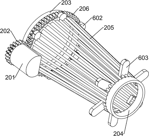
[0030] On the basis of Example 1, such as figure 1 and image 3As shown, the loose bundling mechanism includes a fixed cover 2, a motor 201, a spur gear 202, a large fixed ring 203, a small fixed ring 204, a rolling screen 205 and a ring gear 206, and the left end of the fixed cover 2 is fixedly connected to the third support 103. On the right side, the right end of the fixed cover 2 is fixedly connected to the left side of the fourth bracket 104, the fixed cover 2 is in an inclined state, the motor 201 is fixedly connected to the front side of the fixed cover 2, and the spur gear 202 is fixedly connected to the power output shaft of the motor 201 The rolling sieve 205 is arranged inside the fixed cover 2 in an inclined state, the right end of the large fixed ring 203 is fixedly connected to the left end of the rolling sieve 205, the large fixed ring 203 is rotatably connected to the third support 103, and the left end of the small fixed ring 204 is fixedly connected to the O...
Embodiment 3
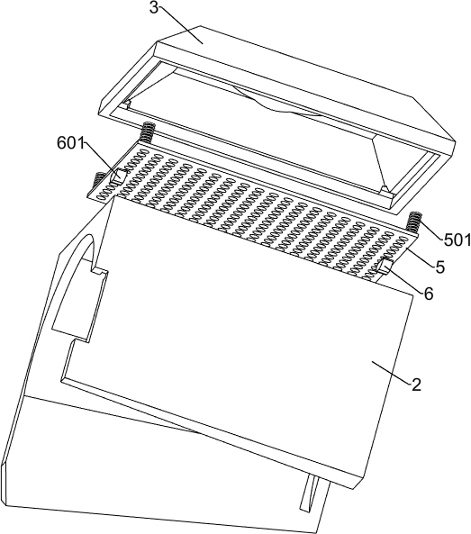
[0033] On the basis of Example 2, such as Figure 2-Figure 6 As shown, the dust collection mechanism includes a collection cover 3, a horn cover 301, a pipe 302, a vacuum cleaner 303 and a connecting pipe 304. The bottom end of the collection cover 3 is large and gradually narrows upwards. A round hole is arranged on the top, and the lower end of the collection cover 3 is fixed Connected to the upper end of the fixed cover 2, the lower end of the horn cover 301 is fixedly connected to the upper side of the collecting cover 3 to seal the round hole, the lower end of the rear part of the pipe 302 is fixedly connected to the upper end of the horn cover 301, and the upper part of the vacuum cleaner 303 is fixedly connected At the lower end of the front part of the duct 302 , the upper end of the connecting pipe 304 is fixedly connected to the lower part of the vacuum cleaner 303 .
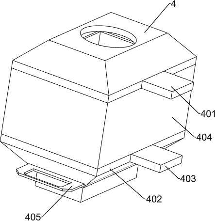
[0034] The dust storage mechanism includes an upper dust storage cover 4, an upper fixed plate 401,...
PUM
 Abstract
Description
Claims
Application Information
 - R&D
- Intellectual Property
- Life Sciences
- Materials
- Tech Scout
- Unparalleled Data Quality
- Higher Quality Content
- 60% Fewer Hallucinations
Browse by: Latest US Patents, China's latest patents, Technical Efficacy Thesaurus, Application Domain, Technology Topic, Popular Technical Reports.
© 2025 PatSnap. All rights reserved.Legal|Privacy policy|Modern Slavery Act Transparency Statement|Sitemap|About US| Contact US: help@patsnap.com


