Two-factor linkage type trigger switch device

A trigger switch and linkage technology, which is applied in the direction of transportation and packaging, circuits or fluid pipelines, vehicle components, etc., can solve the problems of vehicle rollover, not widely applicable to different models, and cannot be automatically restored

Active Publication Date: 2021-07-30
ANHUI UNIVERSITY OF TECHNOLOGY AND SCIENCE
View PDF6 Cites 0 Cited by
  • Summary
  • Abstract
  • Description
  • Claims
  • Application Information

AI Technical Summary

Problems solved by technology

If the vehicle is not equipped with an anti-rollover device, there will be a great danger. In severe cases, the vehicle will rollover, which may easily cause casualties
[0003] At present, the trigger switch device of the existing mechanical anti-rollover device is relatively simple. Although it can effectively exert the anti-rollover effect, there may be the followin

Method used


Image

  • Two-factor linkage type trigger switch device
  • Two-factor linkage type trigger switch device
  • Two-factor linkage type trigger switch device

Examples


Embodiment 1

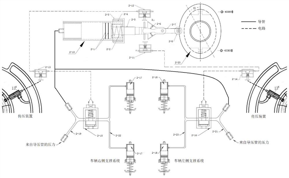
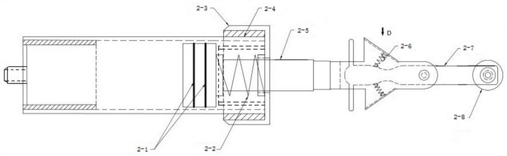
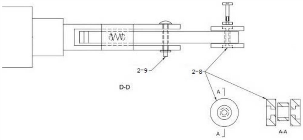
[0037] Such as figure 2 A two-factor linkage trigger switch device shown has a torque loader 2-10 and a corner trigger 2-20, wherein, as figure 2 As shown, the torque loader 2-10 includes an action cylinder housing 2-4 and a piston limit nut 2-3 threaded at the port of the action cylinder housing 2-4, and the action cylinder housing 2-4 A medium cavity and a torque loading piston 2-5 are provided inside, the torque loading piston 2-5 includes a piston head and a piston rod, and a sealing rubber ring 2-1 is provided on the peripheral side of the piston head, and the torque loading piston 2 The piston rod of -5 passes through the piston limit nut 2-3 and connects the linkage switch assembly, and there is also a sleeve set on the piston rod between the torque loading piston 2-5 and the piston limit nut 2-3. Piston return spring 2-2, the medium chamber of the moment loader 2-10 communicates with an external pressure source, and controls the extension or retraction of the piston...

Embodiment 2

[0061] The difference from the above-mentioned embodiment 1 is that in this embodiment, the two-factor linkage trigger switch device can also be applied to prevent aircraft pitching stalls, and this system is applicable to models with different stall speeds and stall elevation angles; At flight speed, it has the function of preventing the aircraft from pitching and stalling.

[0062] Such as Figure 8 As shown, the angle trigger 2-20 is connected with the aircraft control stick, and the linkage relationship between the control stick and the angle trigger 2-20 is: when the control stick is pushed, the angle trigger 2-20 rotates clockwise; The trigger turns counterclockwise.

[0063] The connecting nozzle of the moment loader 2-10 is connected with the aircraft pitot tube, and feels the static pressure of the aircraft pitot tube.

[0064] The trigger switch 2-11 and the trigger switch 2-12 are respectively connected to the horizontal stabilizer control steering gear circuit, a...


PUM


Abstract

The invention discloses a two-factor linkage type trigger switch device, and belongs to the technical field of control switches. The device comprises a torque loader, a linked switch assembly and a corner trigger, wherein the moment loader comprises an action cylinder shell, a medium cavity and a moment loading piston are arranged in the action cylinder shell, and a piston rod of the moment loading piston is connected with the linked switch assembly; the piston rod is sleeved with a piston reset spring, and a medium cavity of the torque loader is communicated with an external pressure source; the linked switch assembly comprises a fork arm and a poke rod hinged to the fork arm, the left side of the poke rod is connected with trigger rods extending up and down, the two trigger rods are correspondingly provided with trigger switches respectively, and the left side of the poke rod is connected with a linked switch reset spring; the corner trigger comprises an oval rotating disc and is provided with a rotating side face capable of being in smooth contact with the pulley. The anti-rollover device can assist in effectively playing an anti-rollover role, and has the advantages that accidental triggering is avoided, rollover early warning can be conducted, automatic resetting is achieved, and the anti-rollover device can be widely applied to different vehicle types.

Description

technical field [0001] The invention relates to the technical field of control switches, in particular to a two-factor linkage trigger switch device. Background technique [0002] When the vehicle is running normally, it will maintain balance due to its own weight. When the vehicle turns sharply (that is, the vehicle speed is fast and the steering wheel turns at a certain angle), the inertia will produce a force perpendicular to the direction of the vehicle's forward direction. When the vehicle's self-weight is added to the When the torque on the wheels is insufficient to overcome the lateral centrifugal force of the car, the car will roll over. If the vehicle is not equipped with an anti-rollover device, there will be a great danger. In severe cases, the vehicle will rollover, which will easily cause casualties. [0003] At present, the trigger switch device of the existing mechanical anti-rollover device is relatively simple. Although it can effectively exert the anti-rol...

Claims


Application Information

Patent Timeline
IPC IPC(8): B60R16/00
CPCB60R16/005
Inventor 高清振高菲潘道远王燕张祖安曹赟博
Owner ANHUI UNIVERSITY OF TECHNOLOGY AND SCIENCE
Why Eureka
Try Eureka